

Linksprite-Yuki
-
Posts
34 -
Joined
-
Last visited
Content Type
Profiles
Forums
Events
Posts posted by Linksprite-Yuki
-
-
Starting with this post, you’ll find on my website a tutorial about the new Arduino Yun: I’m going to blog about my experiments with that board and show its features through real examples… today you’ll learn how to connect it to your wifi network!
Yun and wifi
One of the most useful features Arduino Yun has is the ability to connect to wired (Ethernet) or wireless networks without the needing of an external shield.
I decided to supply my Yun using an external micro USB power supply (power supplies for modern cellphones works fine):

By default, Arduino Yun acts as an access point, broadcasting an unprotected wifi network with Arduino Yun-xx SSID:

After having established a connection, your PC obtains an IP address on the network 192.168.240.0/24:

You can reach the administrative interface of Arduino Yun pointing a web browser to the address http://192.168.240.1. The default password is arduino:

After having logged in, click on configure:

You can change the board’s name (in the screenshot I chose Yun-Luca), the password, the timezone and connect the Yun to one of the wireless networks it detected:

After a reboot, the board will be connected to your network!
Upload via wifi
Now you can use a new feature of Arduino Yun: the ability to upload a sketch using the network, without the needing to connect the board to your PC using a USB cable.
Open the IDE (warning: you must download the latest version, at the moment I’m writing 1.5.4r2) and choose Arduino Yun as your board.
The IDE will scan your network searching for Yun boards and, under the port menu, will display your board and its IP address:

You can now compile and upload your sketch as usual… when the upload process will start, you’ll be prompted for the Yun password:

SSH terminal
You can also connect to your Yun in text mode, using an SSH client (for example PuTTY per Windows)… in the next posts you’ll discover why this can be useful:

For more details,please refer to original post
http://www.lucadentella.it/en/2013/11/05/yun-collegamento-alla-rete-wifi/
-
ZigBee device list
Motion detector Smoke sensor Door detector Water Detector Temperature and Humidity Sensor CO Sensor These ZigBee node devices support ZHA standard protocol.
Linker ZigBee gateway module is one kind of Linker modules which can communicate with up to 32 ZigBee node devices. It is powered by Marvell 88MZ100 ZigBee microcontroller SoC chip. This ZigBee offers advantages for many application scenarios, including lighting control, smart metering, home/building automation, remote controls and health care applications.
Tutorial
we will show how to interface Deepcam ZigBee sensors using the Linker ZigBee gateway.
Prerequisites
Commands to communicate with ZigBee sensor
1. Set Permit Join
Attribute Name Type Note CMD Length Uint8 0x02 CMD ID Uint8 0x75 Permit Join Uint8 0x00 – Always off; 0xFF – Always on; Other values – Turn on permit join for a period of time Example
- Send: [UART] 02 75 1E
- Success response: [UART] 02 8A 00
Note: How to reset ZigBee node device and let it join into the ZigBee gateway?
- Insert the pin to the reset hole and hold, until the green light is blinking very fast.
- If the light blinking is not fast, just release the pin and insert it again until it is blinking very fast.
- This will set the ZigBee sensor into reset mode.
- Send Set Permit Join commands to join
- After a while, gateway will get the response–** New Device Joined Indication**
2. New Device Joined Indication
Sent after ZigBee gateway sends Transport Key to the joining device or received a ZDP Device Announcement.
Attribute name Type Note CMD Length Uint8 0x0E CMD ID Uint8 0xFC Flag Uint8 0x02 Sub CMD ID Uint8 0xE1 -Gateway Special command Short Addr Uint16 IEEE MAC Addr Uint64 Capability Uint8 0xFF – If this indication is sent after Transport Key; Other values – If this indication is sent after receiving the joining device’s Dev Annce Example Transport Key has been sent to a node whose short address is 0x443B and IEEE address is 00:50:43:C9:9F:21:90:6C [UART] 0E FC 02 E1 3B 44 6C 90 21 9F C9 43 50 00 FF
3. Get Gateway MAC Address
Get Gateway IEEE Address Request
Attribute name Type Note CMD Length Uint8 0x02 CMD ID Uint8 0x14 Sub CMD ID Uint8 0x6F Get Gateway IEEE Address Response
Attribute name Type Note CMD Length Uint8 0x0C CMD ID Uint8 0x15 Flag Uint8 0x02 Reserved Uint8 0x00 Sub CMD ID Uint8 0x6F IEEE MAC Address Length Uint8 0x08 IEEE MAC Addr Uint64 Example
- Send: [UART] 02 14 6F
- The Gateway’s IEEE Address is 00:50:43:C9:9F:26:9E:4D [UART] 0C 15 00 6F 08 4D 9E 26 9F C9 43 50 00
4. Set APS Header Parameters
Note:Before sending any other commands in this section, the first step is to set the APS(Application Support Sublayer) Header parameters for the next ZCL(ZigBee Cluster Library) command.
Attribute name Type Note CMD Length Uint8 0x0C CMD ID Uint8 0xFC-ZCL Request Flag Uint8 0x02-ZCL Special Command Sub CMD ID Uint8 0x01 – Set APS Params Profile ID Uint16 0x0104 -Home Automation Src Endpoint Uint8 Dest Endpoint Uint8 Fixed to 0x02 for group mode Dest Addr Mode Uint8 0x01-group address; 0x02 – node short address Dest Addr Uint16 Tx Options Uint8 0x02 Radius Uint8 0x0A Example
- Set source endpoint to 0x01, destination endpoint to 0x01, destination address to 0xAE3E. [UART] 0C FC 02 01 04 01 01 01 02 3E AE 02 0A
- Success response: 04 FD 02 01 00
5. ZDP bind
ZDP(ZigBee Device Profile) Bind Request
Attribute name Type Note CMD Length Uint8 0x16 CMD ID Uint8 0xD8 Source IEEE Address Uint64 Source Endpoint Uint8 Cluster ID Uint16 Destination Address Mode Uint8 0x01 – 16-bit group address for Destination Address and Destination Endpoint Not present;0x03 – 64-bit extended address for Destination Address and Destination Endpoint present Destination Address Uint64 Destination Endpoint Uint8 Example:
- Send: [UART] 16 D8 69 53 37 53 C9 43 50 00 01 05 00 03 1D 4F 28 0F C9 43 50 00 01
- Response: [UART] 02 D9 00
6. Read ZCL Attribute Request and response
Request
Attribute name Type Note CMD Length Uint8 0x08 CMD ID Uint8 0xFC Flag Uint8 0x00-From ZCL Client to ZCL server Cluster ID Uint8 0x00 0x05 Command ID Uint16 0x00 Attribute Number Uint8 0x01 Start Attribute ID Uint16 0x01 0x00 Response
Attribute name Type Note CMD Length Uint8 0x08 CMD ID Uint8 0xFC Flag Uint8 0x03 Cluster ID Uint8 0x00 0x05 Command ID Uint8 0x01 Attribute ID Uint16 0x01 0x00 State Uint8 0x01 Data type Uint8 0x31 Zone Type Uint16 Example
- Send: [UART] 08 FC 00 00 05 00 01 01 00
- Success respone: [UART] 0B FE 03 00 05 01 01 00 00 31 28 00
Zone Type
Sensor Name Zone Type Door Detector 0x15 0x00 Motion Detector 0x0d 0x00 Water sensor 0x2a 0x00 Smoke sensor 0x28 0x00 7. Report configuration
Request
Attribute name Type Note CMD Length Uint8 0x18 CMD ID Uint8 0xFC Flag Uint8 0x00 Cluster ID Uint8 0x01 0x00 Command ID Uint8 0x06 Attribute Number Uint8 0x01 Attribute ID Uint16 0x21 0x00 Data Type Uint8 0x20- Uint8 Minimal Reporting Time Uint16 0x0A 0x00 Maximum Reporting Time Uint 16 0x0A 0x00 Data Uint8 0x01 Timeout Uint16 0x00 0x00 Response
Attribute name Type Note CMD Length Uint8 0x06 CMD ID Uint8 0xFD Flag Uint8 0x00 Cluster ID Uint8 0x01 0x00 Command ID Uint8 0x06 State Uint8 0x00 Example
-
Send: [UART] 11 FC 00 01 00 06 01 00 21 00 20 0a 00 0e 00 01 00 00
-
Success response: [UART] 06 FD 00 01 00 06 00
8. Device Alarm Reporting
Attribute name Type Note CMD Length Uint8 0x15 CMD ID Uint8 0xFE Flag Uint8 0x01 Cluster ID Uint8 0x00 0x05 Command ID Uint8 0x00 Source Endpoint Uint8 0x01 Source address type Uint8 0x02-Short address Source address Uint16 Reserved Uint32 0x00 0x01 0x00 0x00 Zone State Uint16 0x21 0x00 Reserved Uint24 0x00 0x00 0x00 Example [UART]15 FE 01 00 05 00 01 02 7B D0 00 D0 00 01 00 00 21 00 00 00 00 00
Sensor state
Sensor Name Open/Activated Door Detector 0x20 0x00 Motion Detector 0x21 0x00 Water sensor 0x21 0x00 9. Battery level reporting
Attribute name Type Note CMD Length Uint8 0x13 CMD ID Uint8 0xFE Flag Uint8 0x03 Cluster ID Uint8 0x01 0x00 Command ID Uint8 0x0A Source Endpoint Uint8 0x01 Source address type Uint8 0x02-Short address Source short address Uint16 Unkown Uint16 0x00 0x4B Reserved Uint32 0x00 0x01 0x00 0x00 Zone State Uint16 0x21 0x00 Data Type Uint8 0x20-Uint8 Battery Level Uint8 Example Receive: [UART] 13 FE 03 01 00 0A 01 02 6D 4B 00 4B 00 01 00 00 21 00 20 BC
Battery level = (0xBC/2) %= 94%
10. Unbind Device
Request
Attribute name Type Note CMD Length Uint8 0x0C CMD ID Uint8 0xE4 IEEE Address Uint64 0x00 0x00 0x00 0x00 0x00 0x00 0x00 0x00 Type Uint8 0x00 Target Short Address Uint16 Source Endpoint Uint8 0x01 Reponse
Attribute name Type Note CMD Length Uint8 0x0A CMD ID Uint8 0x7B IEEE Address Uint64 Type Uint8 0x00 Example
- Send: [UART] 0C E4 00 00 00 00 00 00 00 00 00 AA BB
-
Response: [UART] 0A 7B 69 53 37 53 C9 43 50 00 00
Note: When you use gateway send command to ZigBee node device and want it response, you have to make sure the ZigBee node device is not in sleep mode, or you will always fail to communication with ZigBee node device. You can click the reset hole to activate the ZigBee node device.

For more details,please refer to original post
https://github.com/YaoQ/zigbee/blob/master/zigbee-sensor-tutorial.md
-
Summary
DHT22 module applies specific digital blocks collection technology and temperature and humidity sensing technology to ensure that products with high reliability and excellent long-term stability. Sensor comprises a capacitive humidity sensing element and a high-precision temperature component, and with a high-performance 8-bit microcontroller connected. Therefore, the product has excellent quality, fast response, anti-interference ability, high cost and so on. Measurable temperature range of the module: -40-80 ℃ ± 0.5 ℃, humidity range: 20-90% RH ± 2% RH. The module is widely used in temperature and humidity regulator, weather station, and other relevant temperature and humidity detection control.
Material preparation
- LinkNode D1 x 1
- DHT22 x 1
- DuPont line
- Arduino IDE
Steps
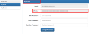
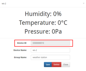
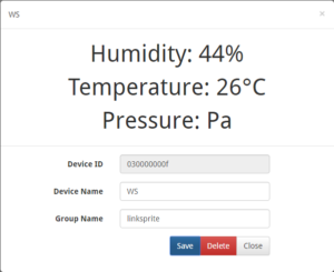
1. Login linksprite.io ,record the “Device ID” and “API key” ( If there is no account, please sign up. )
- 1. My Profile -> API key
- 2. My device->Create DIY Device
Enter Device Name,Device Type , Group Name , the device number is 03, device name and device grouping can be any.

Note: Device Type must be selected 03(Custom device type) .
Click the device you created and record the “Device ID”.
2. Edit and run the code
Modify the “apikey” and “deviceID” with content acquired before
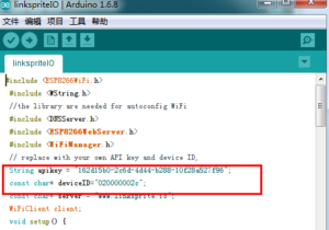
Compile the code and upload.
3. Results
- Serial Monitor
 2. LinkSprite IO
-
Functions and descriptions:
- Perpetual calender: from 1st/January/2000 to 31st/December/2099;
- The hour display format can be set between 12 hour format or 24 hour format. The time zone can be setfrom-12 to +12 (user setting);
- Daylight saving time is adjusted automatically (The daylight saving time is adjusted on the basis of differenttime zone);
- The date display format can be set as: YYYY-MM-DD,MM-DD- YYYY,DD-MM-YYYY(user setting);
- The RCC time function can be set between DCF mode or WWVB mode; In RCC mode, press any key to quit;In British, DCF signal can be received entirely.
- Wireless 433 MHZ receiving. Available distance: 100 meters in outdoor open field. While receiving RF, pressany key to quit;
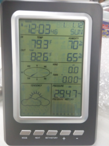
- Indoor/outdoor relative humidity (RH %) display. Display range: 20% to 99%. Resolution: 5%;
- Indoor/outdoor temperature display. Display units options: ℃/℉(user setting). Indoor temperature range:0℃ to +50℃; Outdoor temperature range: -40℃ to +60℃; Resolution (for both indoor/outdoor temperature):±1℃
- Wind-chill temperature display. Display units options: ℃/℉(user setting);
- Dew-point temperature display. Display units options: ℃/℉(user setting);
- Atmospheric pressure (absolute pressure and relative pressure) display. Display units options: Hpa, Inhg ormmhg (user setting). Pressure display range: from 750hpa to1100 hpa;
- The trend of the atmospheric pressure can be displayed via histogram. The time format can be set between12H format or 24H format (user setting);
- Wind speed and wind direction display. Average wind speed and gusts display. The units can be set asm/s,km/h,mph,knots or bft ( user setting ). Wind speed range: 0 to 50 m/s; Wind direction range:E,S,W,N,SE,NE,SW,NW;
- Rainfall can be displayed on the basis of hour, day, week, month or total. The unit can be set between mm orinch (user setting); Available total rainfall is 9999mm;
- Sunny, cloudy, overcast, rainy, snowfall, rainstorm can be forecast and displayed via six corresponding icons.These icons indicate different weathers and weather tendency;
- All maximum/minimum data can be recorded and displayed. In addition, the time of recorded data can bedisplayed as well;
- The weather alarm can be set separately, any value can be set. The alarm signal lasts 2 minutes;
- LED backlight. Press any key, backlight will be activated and lasts 10 seconds;
- Indoor/outdoor low voltage detection. Sign flash appears while low voltage;
- Consumption: 3*AA 1.5V Alkaline batteries or DC 5.5V transformer (electric current bigger than 100mA).
How to set up
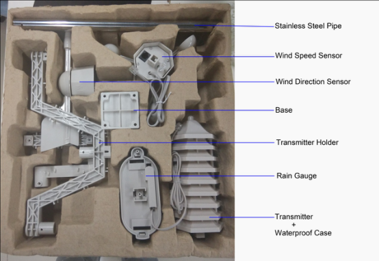
1.Open the box

2.Refer to the manual and install the components.
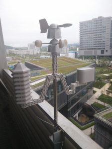
3.Power on (install 3 x AA 1.5V) the indoor receiver first, and then install the batteries (2 x AA 1.5 V) in the outdoor transmitter, Pls DON’T have any button operations during this period, and keep WAITING for 10 minutesin order to let the indoor receiver has enough time to complete the signal matching. The data of the transmitter will update every 48 seconds. The screen of the receiver will show as below picture:
4.Setting parameters according to the manual. And you can start to enjoy the pleasure of this weahter station.
Link: http://linksprite.com/wiki/index.php5?title=WS1030_Wireless_Weather_Station_with_Solar_Sensor
-
We are seeing an increased need to track a object in real time and view its position on a mobile phone. There are many different places that users want to install the GPS tracker, but a rigid enclosure like what the market currently has cannot meet all the requirement. Openhapp offers this DIY GPS tracker kit to service the DIY market where users can use encosures, batteries, antenna to fit their need. This GPS tracker posts its position and battery level to LinkSprite.io at a configurable time interval, a mobile APP is also provided to get the position and battery level from LinkSprite.IO and show the location on the mobile APP.
To add the device to a user's account is done by using the mobile APP to scan the QR code supplied with the kit.
If you find that this GPS tracker doesn't fit your need exactly, please contact us and we can custom make for you.NOTE:
This GPS tracker uses GPRS, and AT&T doesn't offer this service anymore. We have tested with T-Mobile.Connectors:


- 1 - MiniUSB interface. This is for power supply and can be used to power the board or charging the battery if the battery is attached. With the UART to USB adaptor, it can also be used to communicate with he GPRS/GPS module.
- 2- SWD programming header
- 3- Power on/off button
- 4- GPRS/GPS module
- 5- GPS antenna connector
- 6- GSM antenna connector
- 7- Bluetooth antenna connector
- 8-DS4 power on indicator
- 9-DS3 GPS acquire location success indicator
- 10- DS2 Reserved
- 11- DS1 Charing indicator
- 12- STM32F103CBT6 MCU
- 13- MicroSIM card socket
-
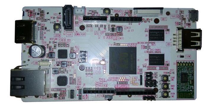
pcDuino3B is a high performance, cost effective single board computer. It runs operation systems such as Ubuntu Linux and Android. pcDuino3B has HDMI interface to output its graphic desktop screen. It could support multi-format 1080p 60fps video decoder and 1080p 30fps H.264 and MPEG4 video encoder with its built-in hardware video processing engine. It targets specially the fast growing demands from the open source community. pcDuino3B provides easy-to-use tool chains and is compatible with the popular Arduino ecosystem such as Arduino Shields.
-
The Mbed BLE Sensors tag is a bluetooth 4.0 BLE sensor development board that is powered by Mbed. It integrates powerful devices, such as NRF51822, LIS3DH ,BMP180, buzzer, and dual-color LED. It also embeds an mbed compatible programmer to make program and download application very convenient.
The mbed BLE sensors tag is consisted of two modules: one is a bluetooth 4.0 BLE sensors tag powered by NRF51822 which is a Bluetooth Low Energy & 2.4GHz Wireless SOC. This mbed BLE sensor tag is mbed-enabled device which simplifies and speeds up the creation and deployment of bluetooth devices based on ARM micro-controllers. There is an mbed library supporting BLE sensors tag which provides the C/C++ software platform and libraries, and can speed up your BLE application development.
The other one works as a programmer like Jlink, but it is compatible with ARM’s mbed. It greatly simplifies the programming process. You just copy the compiled hex file to an emulated disk, which is recognized by PC when you plug this programmer into the PC and the programmer will automatically download the program into BLE SENSORS TAG without any other setting.


How to use debug port to quickly access pcDuion8 Uno
in Feedback/Comments
Posted
There is a debug port on pcDuino8 Uno which can used to access system directly as command line mode. You just only use a USB UART cable to connect to this port, when system is up, system initialization information will print to this port and also you can use it to log in Ubuntu. It seemly like an Linux terminal and you can control the whole system without screen, keyboard or mouse. Very convenient, isn’t it?
The following part will tell you how to use this debug port.
1. Get a USB UART cable
I use this PL2303 USB UART cable, and the details has been shown in the following table.
2. Install Drivers on PC(Windows as example)
Download the PL2303 Windows driver and install it.
3. Connect
One port of USB UART cable is connected to PC USB port。Another pins are connected to debup port on pcDuino8 uno.
4. Configure the Serial tool
Open Device Manager to get which COM port has been recognized by PC.
Open a serial tool(take Putty as example) and configure it:
Serial line :COM11
Speed:115200
Then click “Open” button.
Power on pcDuino8 Uno, the log information will print on the window.
At the end, it directly login ubuntu as root, and you can input shell command to control the system.