

ling1995
-
Posts
3 -
Joined
-
Last visited
Content Type
Profiles
Forums
Events
Posts posted by ling1995
-
-
Respected sir:
Good day. Recently I am resting in my home cause some reasons. I was boring and I decided to design circuit.I have a big interest in electronics. However, my professional knowledge is still limited. So here I am.
 but maybe it's simple for you.Please help me out!
My situations are as followings:
I myself design a circuit,but it don't work ! I chose INA331IDGKT cause it's rail-to-rail output,low-cost and low-power.Why it can work in the ORCAD 16.3 ? I have already built the INA331IDGKT library files and symbols before I use it.If you need more details about hardware,please refer to the datasheet of INA331IDGKT.
Best regards~
-
Hello~all,it's my first time to be here.I hope I chose the right forum to ask for help for my project !
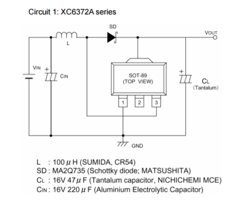
In my project,I need to use boost circuit and I rose the battery from 3.7V to 5V. After that,The chip--XC6371 (this one) was surely chosen.According to it’s datasheet, I design a boost circuit.Unfortunately, I can’t get a right voltage of output whatever I did. The outputted voltage is lower than the inputted voltage.Anybody who have used it can help me? I have upload the schematic diagram,please have a look. In my circuit,the capacitor of 47uf has used in the outputted port while the another one with 220uf in the inputted port. Others I used is 100uf. Anybody can help me? Any suggestions ?
Thanks a lot !
PS: This is the circuit,please have a look!
DIY a Compact RC Switch
in Electronic Projects Design/Ideas
Posted
Good day~all,
I have made a compact RC switch circuit,which built around the LM358 comparator reacts to a 50Hz PWM signal with a pulse width of around 1-2ms. If the reference voltage ( at pin2 of LM358 ) fixed by the 10K oitebtuineter is lower than the filtered signal voltage (at pin 3 of IC1), the comparator output goes high, relay driver BC547 (T1) is switched on and the 5V relay (RL1) works. The 100K reistor ( R5) provides small hysteresis to prevent the comparator from responding to every minor wavering in the voltage on the non-inverting input (pin 2) of the comparator. The aim I bluit this circuit is to control the on/off of lighting on radio control projects.
Well,Comparing with the above circuit,the only differences are that
1).The relay driver(T1) I used is BC547A instead of BC547. This is the BC547A PDF.
2).My circuit has a 20K pot and it will not work,I am having a hard time figuring out the pin 2 input,giving a negative voltage.
Can anyone here help me?
Best regards~