

Amiir
-
Posts
3 -
Joined
-
Last visited
Content Type
Profiles
Forums
Events
Posts posted by Amiir
-
-
On 7/28/2017 at 6:39 AM, audioguru said:
If you use fine and coarse controls then one will always be in the wrong position. Use larger knobs instead.
Higher output current will cause a heat problem in the output and driver transistors. The improved version of this project already uses two output transistors to share the heat produced at 3A. Use a huge heatsink and a fan for 4A output. Change R7 to be 0.35 ohms/10W.
A 24VAC transformer is too low for this project to produce 30VDC output at 3A or 4A but the original TL081 opamps will have a voltage too high for them if the transformer voltage is increased. The improved version of this project uses TLE2141 opamps rated at a supply of 44V and a 28VAC or 30VAC transformer.
A transformer rated at 24V/4A has a limit of 24V x 3A= 72VA. But here the 24V is rectified to produce a peak voltage of 34V. Then if the load on this project is 3A the transformer produces 34V x 3A= 102VA. It must be rated for 102VA/24V= 4.25A. If the output of this project is 4A then the transformer must be rated for 5.7A.
thank you so much for your reply sir.

forget about using hi amp switching power supply instead of transformer. it was just a Curiosity question.
but about increasing the output amperes as you said for taking 4A from output i should change my transformer with 24v 5.7A.
so if i use 24v 4A transformer then how much amperes i can take from output?
cooling 2N3055 is not a problem. best heat sink and turbo fan used for that.
each 2N3055 can handle how much amperes in best cooling situation ?
QuoteIf you use fine and coarse controls then one will always be in the wrong position. Use larger knobs instead.
in Chinese power supplies coarse and fine works well. they use same opamp and other parts for that.
volumes are :
Voltage Coarse : 50K - Voltage Fine : 5K
Current Coarse : 10K - Current Fine : 1K
QuoteUse larger knobs instead.
before i asking my questions here i decided to use larger knobs as you said. but fine volume works better.
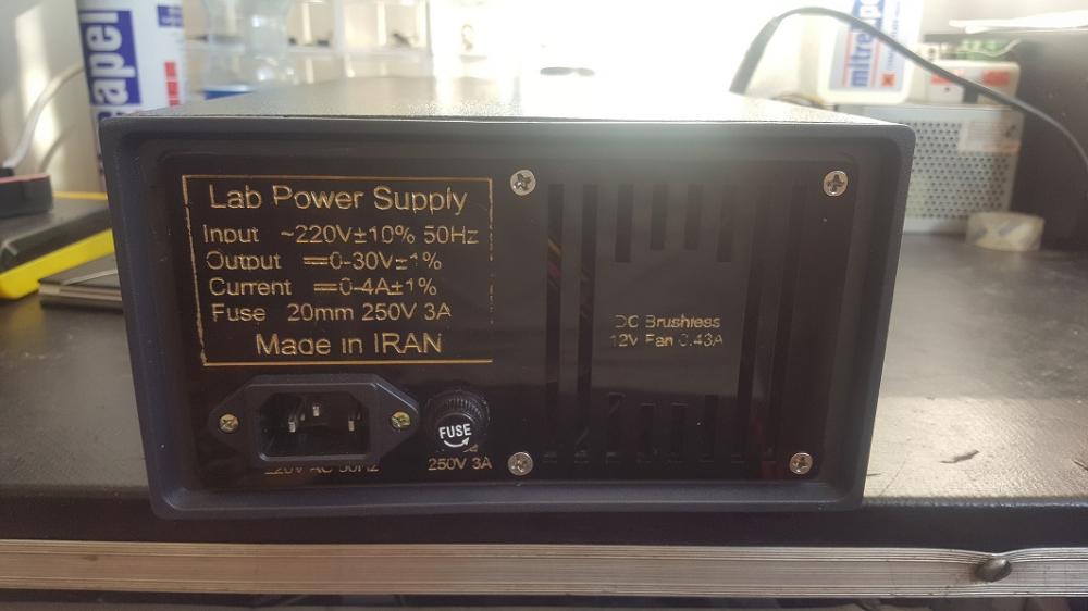
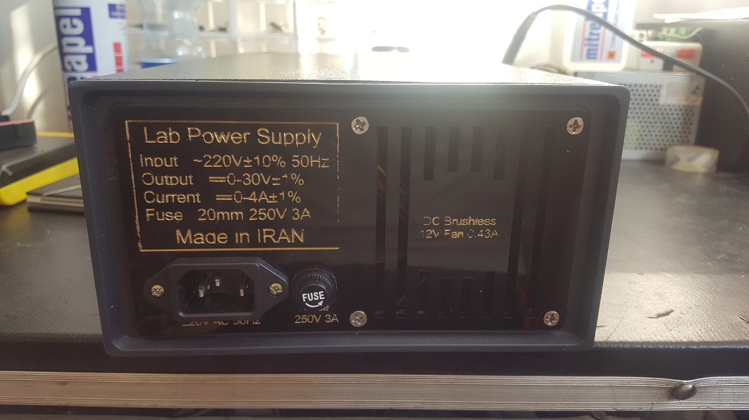
*i just completed the rear panel laser cutting file Designed with extreme accuracy.
so if anyone use the box just like mine then he/she can use this files without any changes.
but of course you can change it as you like.
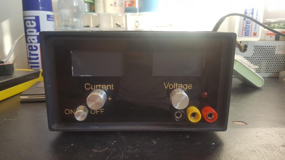
the front panel will be done soon.
ebay link for used parts will be placed here.
-
hey guys. im new here.
i made this power supply for my small workshop and i have some question about it.
first Q : how can i add Fine volume for voltage and current! (Coarse and Fine)
second Q : this circuit cut off the output voltage when we take more than 3.0 Amperes. its ok. but my transformer can deliver 4.0 Amperes and i want to change this cutoff option to 4Amp.
third Q : can we use 24v 10a (or 30v 10a or 48v 10a) Switching power supply instead of transformer in input and make it more powerful ?
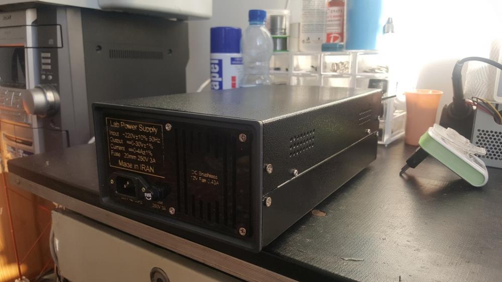
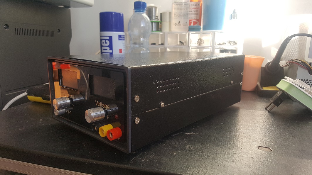
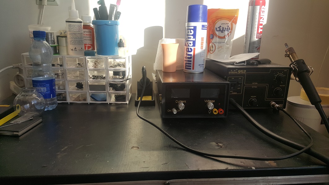
thanks guys. in attachments you can see my power supply v1.0

i make this one for my friend and now im about make another one for myself.
please answer my question. after completing the project i will upload Corel Draw files (Front and Rear Panel Plaxi Laser Cut)
* That "Made in IRAN" is just for fun
all parts purchased from china 
images are for v1.0. in this new one i made a lots of changes in front and rear panel.
this one has no volt/amp meter yet. but the rectangular cuts are place for them.
thanks guys and im sorry for my bad english


0-30 Vdc Stabilized Power Supply
in Projects Q/A
Posted
i dont understand. in projects Bill Of Material said use 24v 3a Transformer for making 0-30v 0-30a power supply.
but u said if i use 24v 4a i will get 0-30v 2.8a !? how can its possible ?
so if we use 24v 3a transformer we will get less than 2.2a! so its not 0-30v 0-3a dc power supply!
the circuit current cutoff (short circuit protection) is 2a or 3a?
if its 3a and we use 3a transformer for making project (taking 2.1a) its never cutoff the output for short circuits!
anyway my heat sink were bought from local stores and they do not provide datasheet for this items!