

detonatorinf
-
Posts
16 -
Joined
-
Last visited
-
Days Won
1
Content Type
Profiles
Forums
Events
Posts posted by detonatorinf
-
-
2 hours ago, audioguru said:
Each comparator in an LM339 has an output current of only 4mA. Relay coils need more current so transistors or Fets must be in between.
Your block diagram is missing the huge filter capacitor needed that might burn out the relay contacts when the relays switch taps.
I
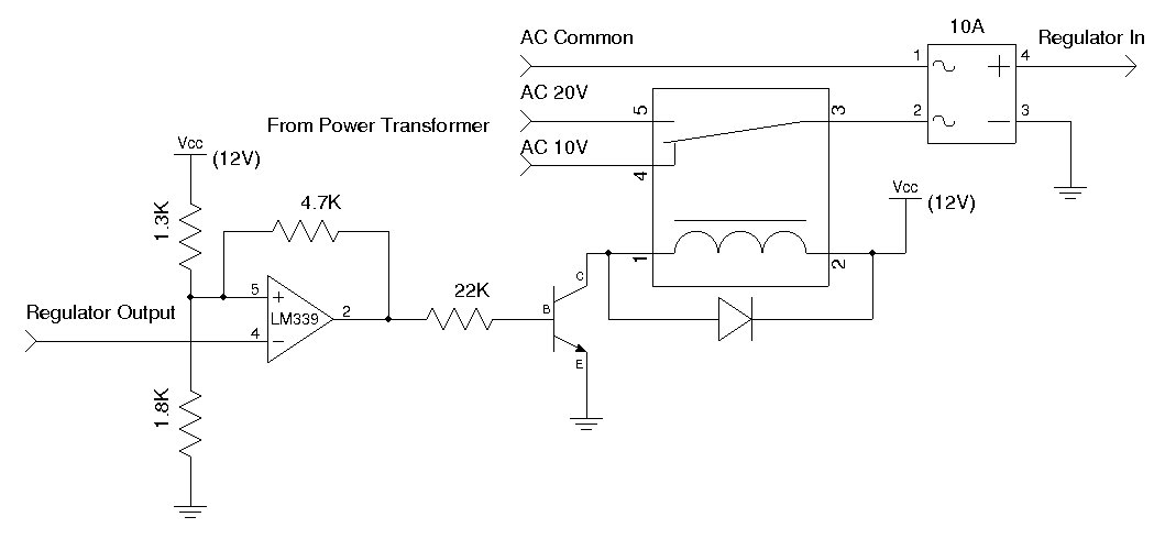
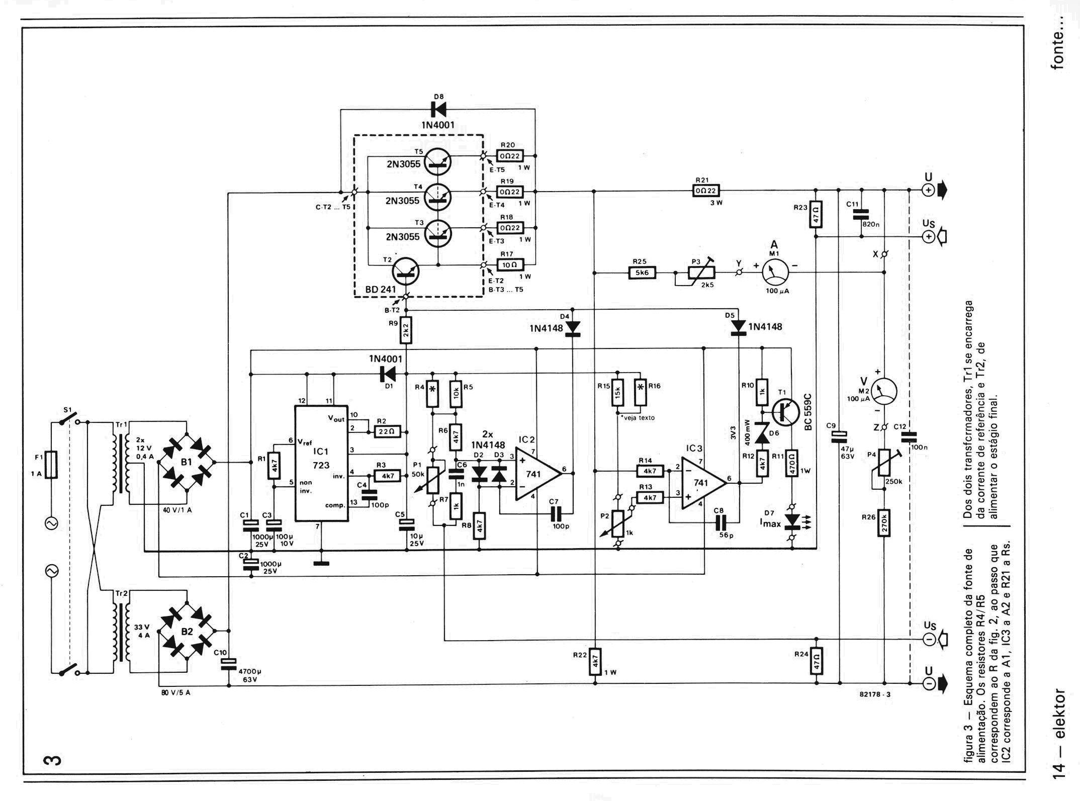
I was thinking about the tap selection circuit being done before the rectifier diodes and filter capacitors. This image relates to a similar aproach using the lm338. Since the mc34071 needs a stable 40v supply and -1,4v. Another 28vac 600ma transformer is used for powering the opamps and generating the negative supply. Most of my concerns are about the right way to connect the second transformer.
-
Hello everybody. What modifications should i consider for making this project? My idea is:
1- A huge transformer with two 28v secondarys. One secondary has a low current for only driving the current and power regulation. Another secondary will deliver the high current and has multiples taps. Both have their own rectifier boards.
2- A voltage comparator will take care of the tap selection based on the output voltage of the power supply. A way to reduce power dissipation. I'm thinking about the lm339 or three lm311 and relays.
I already made the transformer and i'm following the guide of a Youtube user who made the same modifications on the tl081 version of this power supply. This is basically how he explained the concept. This approach is similar to the elektor power supply but without the tap selection circuit.

-
1 hour ago, audioguru said:
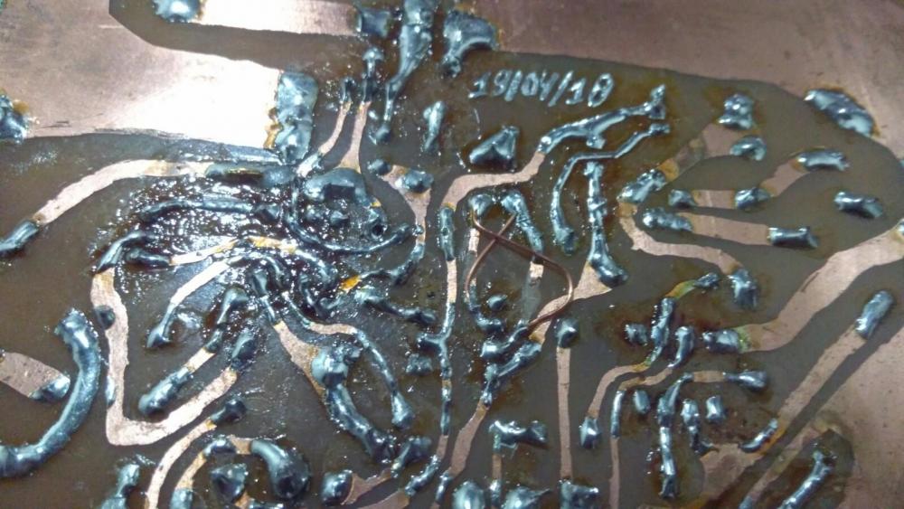
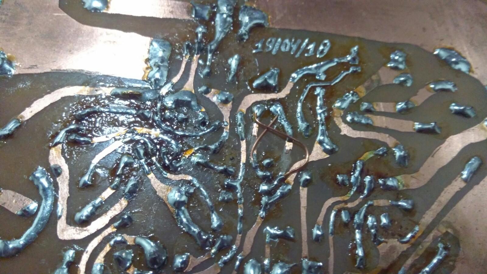
Surface mount ICs on adapters? Solder that was dripped on from up high and heated with a blow torch?
All I can say after seeing your project is "EEK!".
Hahahaha. I promise i will make a better one.
-
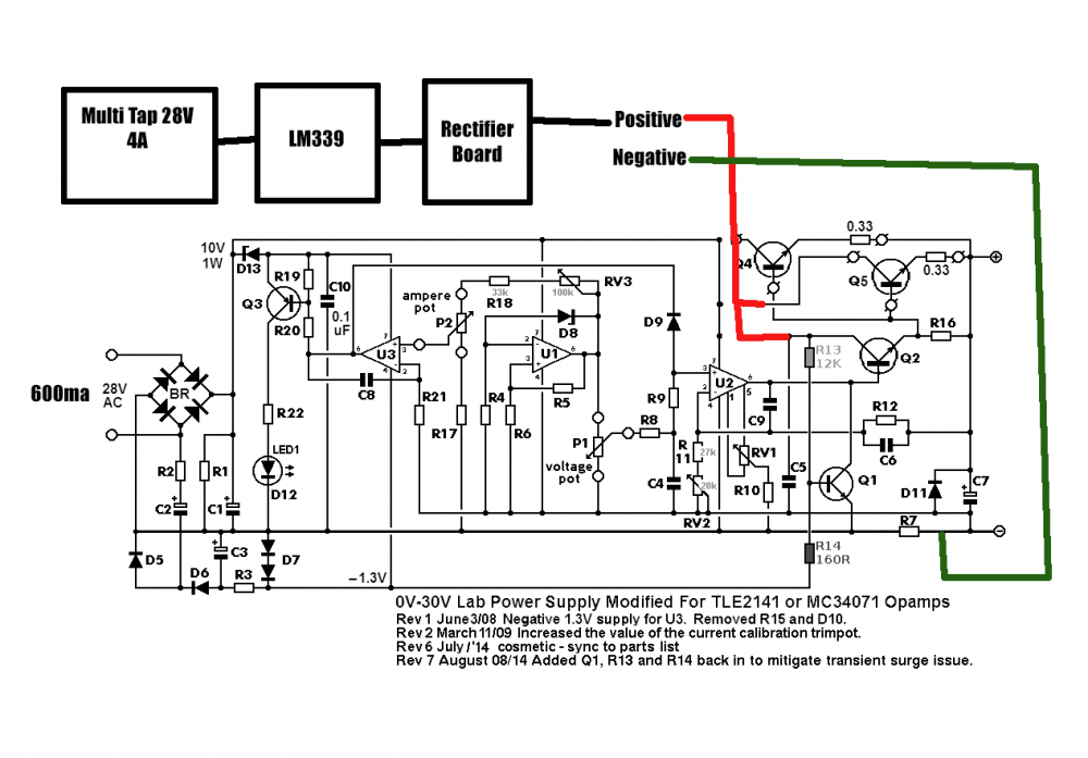
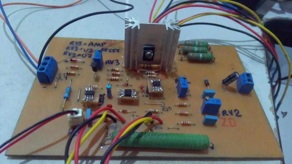
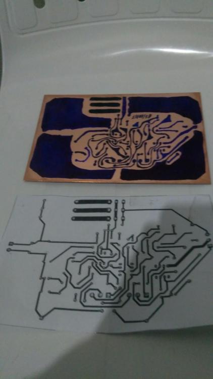
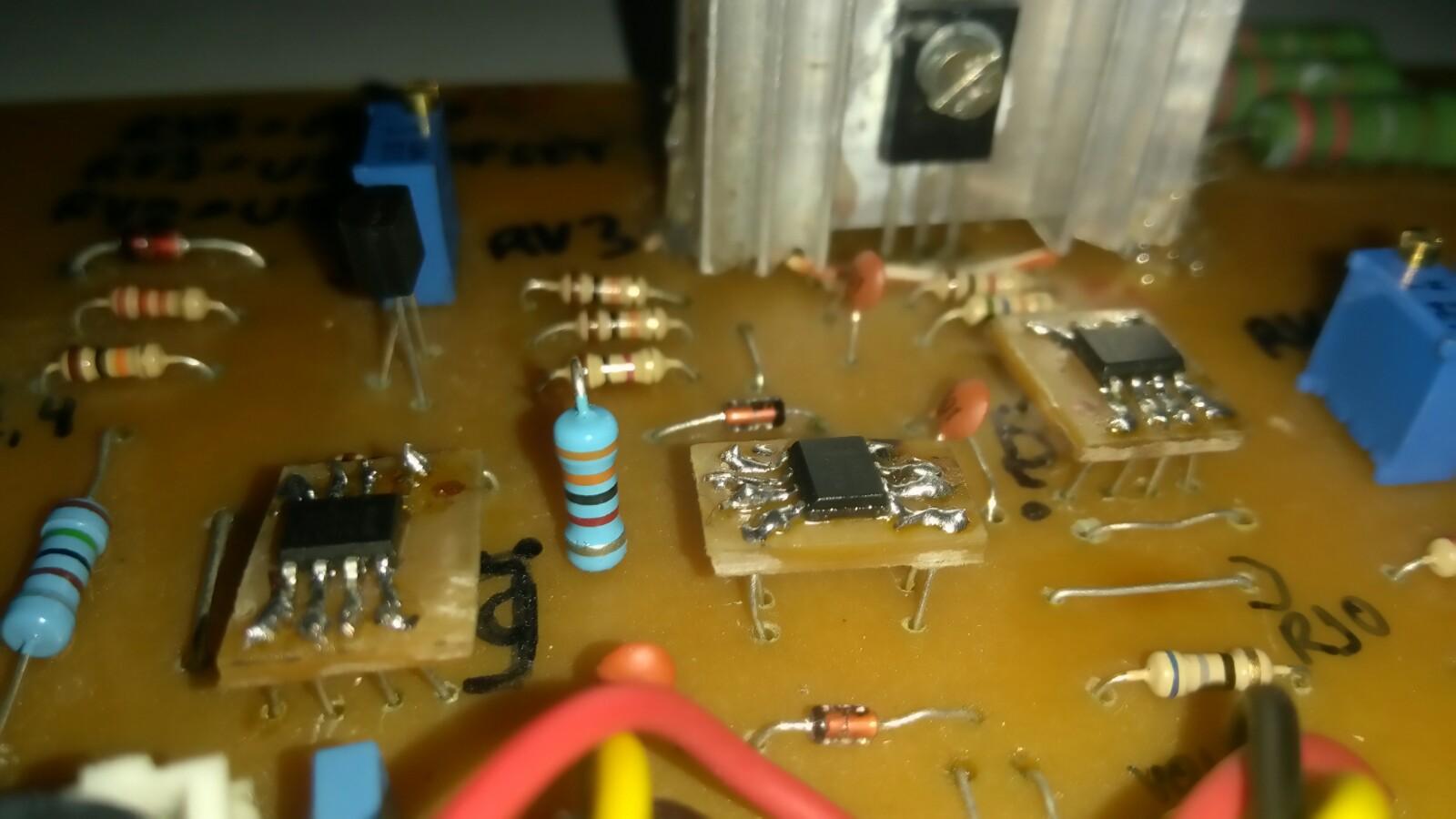
Sorry, audioguru. My post sounded like i was describing how the circuit should work but i was just explaining the behavior of the opamps. None of the 3 opamps were working as intended. The problem was caused by my lack of atention while copying the schematic to Kicad. The opamp footprint for U2 was printed with the negative and positive inputs inverted. Two jumpers solved the problem and now i have a working power supply. I attached some images.
Really ugly, ain't it? But it was my first time learning how to make one.
R7 resistance is 0R22. I couldn't find the 0R25 resistor recommended for a 5A power supply. Also, three 2sc5200 in parallel are used as output transistors.

-
4 hours ago, audioguru said:
My Rev 6 July, 2014 schematic shows that opamp U1 makes the 11.2V reference, U2 is for the voltage control and drives the output driver transistor with 0V to about +32V and U3 is for the current control and has an output from -1.0V to about +27V.
If the output has a low voltage (or is shorted) and a high current then the NPN output transistor in U2 will get hot. A tiny little surface mount package cannot dissipate much heat.
Sorry. You're right. I confused the order of the ICs. U1 (reference voltage) outputs 33v and U2 (voltage control) outputs 0,640V to the base of the BD139.
-
2 hours ago, audioguru said:
I did not calculate it but I think a tiny surface mounted opamp for position U2 will get too hot if the hFE of the driver and/or output transistors is low.
U3 only outputs 0,640 volts. When the voltage control pot is rotated to the left or right, the variation in the readings are minimal. The voltage only raises to 10v when U3 gets too hot. U1 outputs 33v and also gets hot. RV2 has no effect on the readings.
-
Wow! After long 4 months of waiting, my package with five TLE2141CP finally arrived from China. And for my "surprise" none of them worked. Both U1 and U3 got extremely hot and began to smell. Turns out two resistor got burned!!
Just minutes ago i found a store in my country that sells the original MC34071. God... so much time wasted. I'm ordering them tomorrow ASAP.
Just a advice for Brazillians interested in building this project. The online store Proesi is selling the SMD version of the MC34071.
-
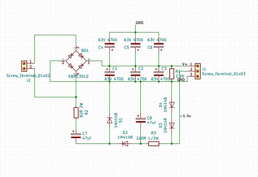
Thank you, Tintin. Adding another 2k2 resistor in parallel solves the problem. Now the rectified voltage is 40,5 VDC and will not rise.
-
Then i should assume that my 30.5VAC transformer has a number of widings for a 29.5VAC. The widings are at a ratio of 2,44 turns per volt. So i need to remove 2 or 3 turns to get something near the ideal 28AVC.
-
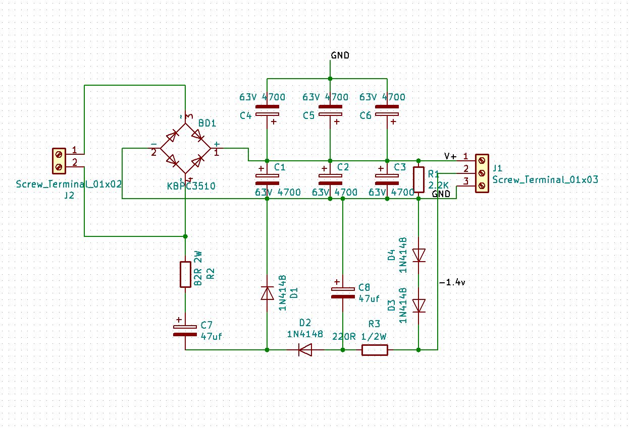
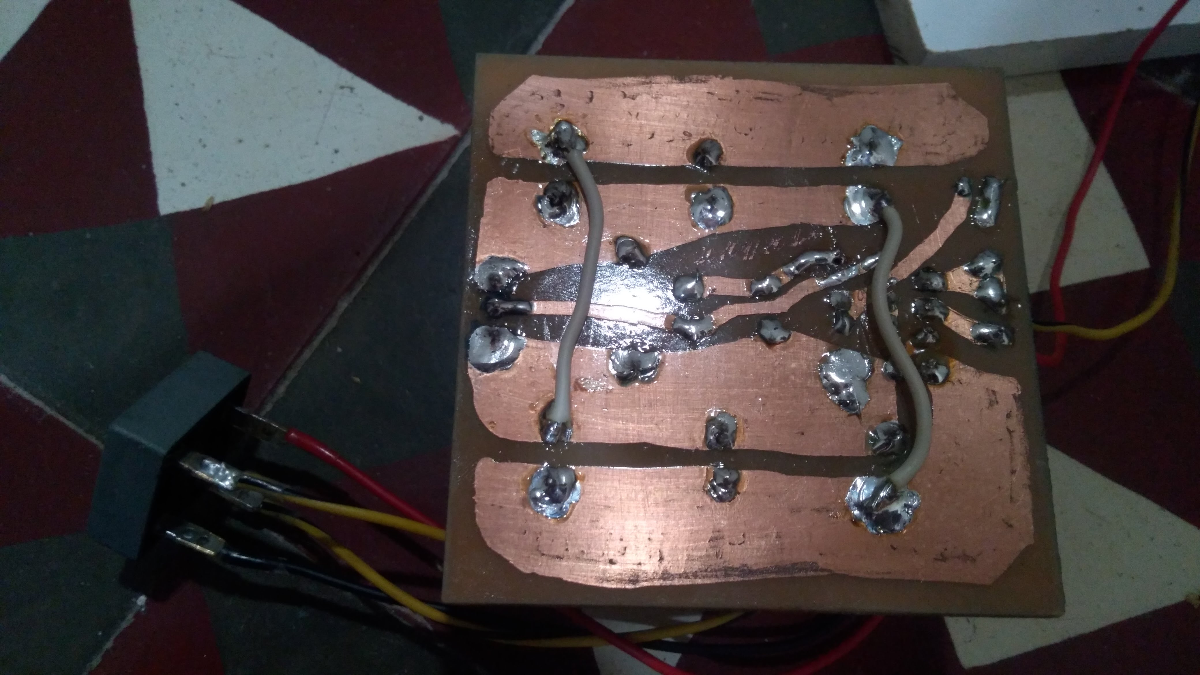
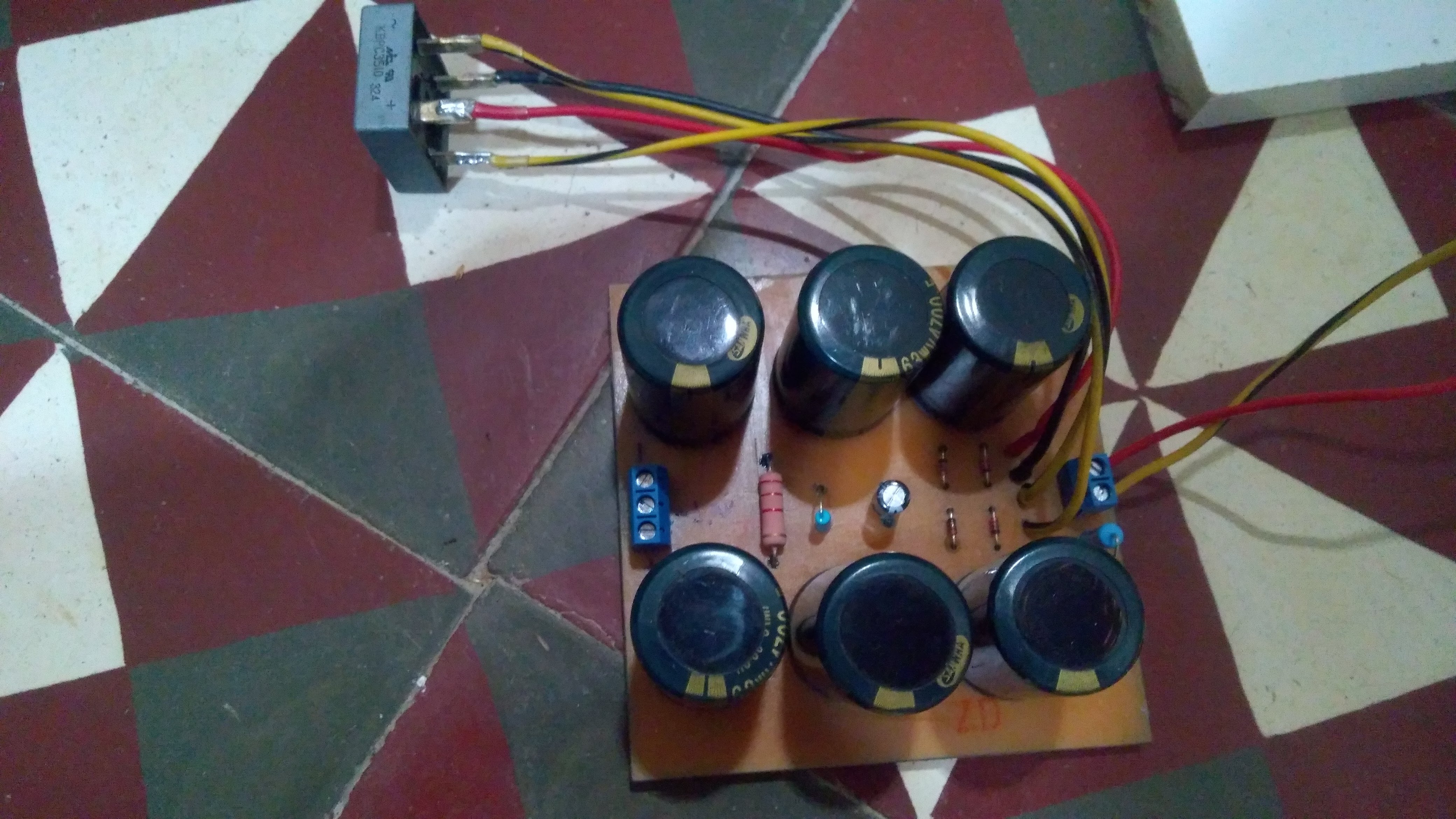
Hello. I have a question about the rectifier part of this project.
I recently made a transformer and a rectifier board that outputs the GND, 30VDC and -1,4VDC lines. Since the winding was made by hand, the output voltage got a little off. Instead of a 28AC output, i got something around 30,5AC. The problem starts when i connect the transformer to my rectifier board. The positive output gets to 45VDC and begins to slowly rise until it hits 49VDC. The negative line stays at -1,6V. I'm more worried about the positive supply since the OPAMP can only take 44Volts.


-
What is the consensus about the voltage spikes discussed on older posts? REV8 adds a darlington transistor to solve this problem. But even after that, other solutions are still being presented for the same problem.
-
2 hours ago, audioguru said:
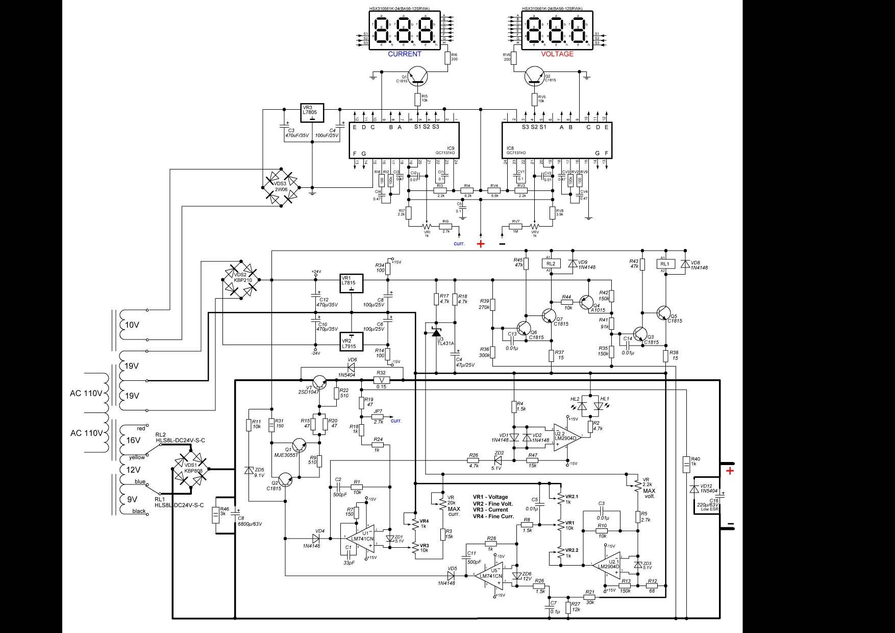
The Chinese power supply uses relays to switch the transformer voltage into voltage ranges so that the output transistor does not get too hot. I do not know if any parts are overloaded and I do not know how good or bad is its regulation. Its LM741 opamps were designed 50 years ago (!).
Thank you.
I will choose this project in that case.
-
Quote
Your photo of a no-name-brand Chinese power supply does not show any specifications and does not show its schematic and parts list.
I found this. Since the same model number is shared by other 4 brands. I can't tell if the actual hardware still true to the schematic.

-
I'm referring about this model.

-
For months I've been reading threads about this project to get some confidence boost in building my own. But at first, my plan was to buy one of these cheap chinese power supplies that provides 30v at 5Amps. My question is about the stability of those chinese power supplys compared to this project. Would be better to invest time building this project or go the easy route?


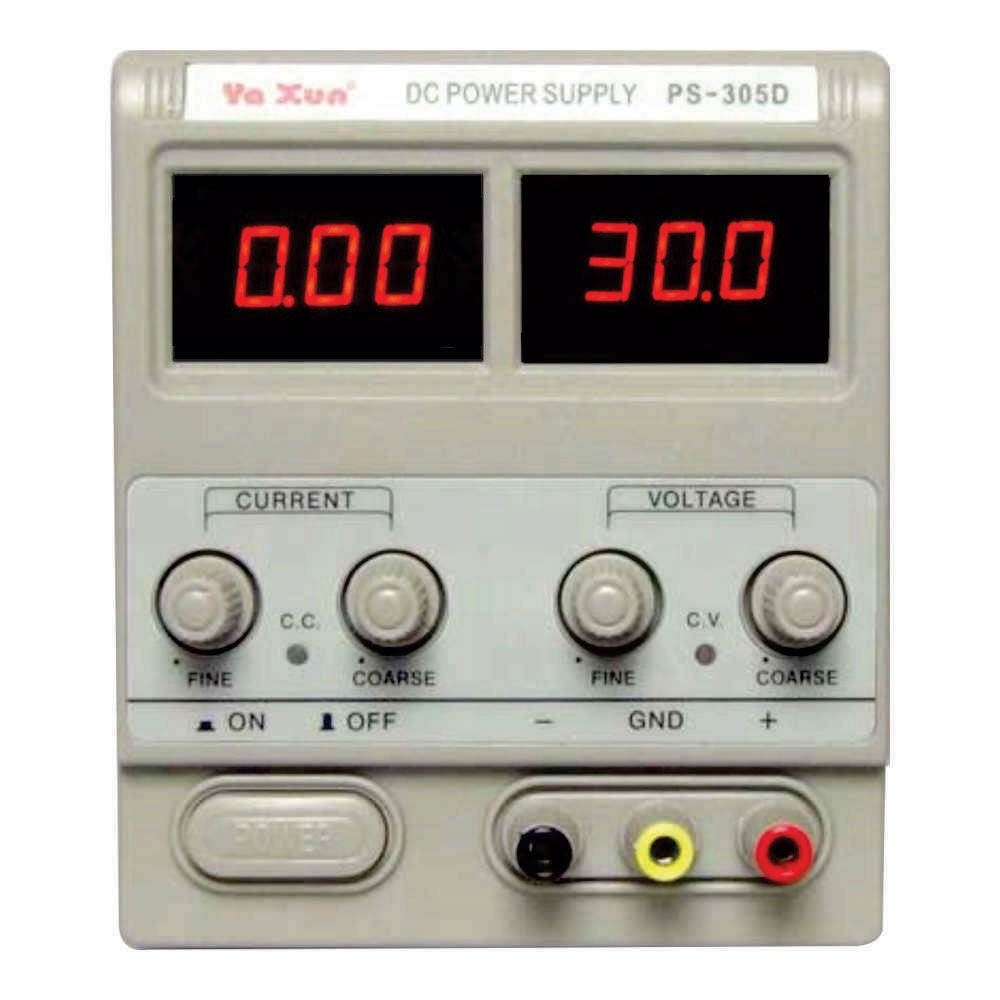
0-30 Vdc Stabilized Power Supply
in Projects Q/A
Posted
Sorry. I was aware of the pullup resistor. I will stop from here and stay with the standard project. I will stick with the lm311 and a lm35 for cooling the heatsink.
Once again, thank you for your help and patience, audioguru.