You should draw the fuse F1 as a blown fuse, you have a short circuit by the wire/conductor on the left. That was a test right? To see if anyone really looked at it 😉 Isn't the 7805 a voltage regulator? Not a flasher?
What are the" flashers" connected to? Shouldn't they connect to the anode leads of the LEDs rather then the LEDs connecting to the Low Beam Terminal?
What happens when the left and right flashers and the hazard flashers are on at the same time? Maybe okay. Could the DPDT switch be replaced with a SPST switch? Also on your SPDT there is no off position.
Otherwise the schematic looks better than my poorly hand drawn schematics.
This was not a test. This circuit works. Those are flashers, they get power from 12 v battery and the out terminal the "load" terminal goes to each switch. The DPST has just the off or on position to turn on both led's at the same time and the flasher, flashes them at the same time.
"Could the DPDT switch be replaced with a SPST switch?"
It's a DPST switch it feeds both led's with 1 throw.
Hi all,
New to electronics, found circuitlab and I made a car turn signal hazard light schematic. I would like to know if I did it correctly "the layout" any tips appreciated
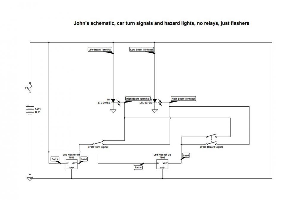
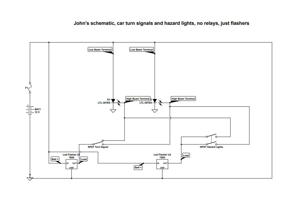
How is my schematic layout and design
in Electronics chit chat
Posted
This was not a test. This circuit works. Those are flashers, they get power from 12 v battery and the out terminal the "load" terminal goes to each switch. The DPST has just the off or on position to turn on both led's at the same time and the flasher, flashes them at the same time.
"Could the DPDT switch be replaced with a SPST switch?"
It's a DPST switch it feeds both led's with 1 throw.
Thanks for liking my schematic.