

G_i_o
-
Posts
3 -
Joined
-
Last visited
Content Type
Profiles
Forums
Events
Posts posted by G_i_o
-
-
On 4/14/2020 at 4:00 PM, Michael Zhang said:
The focus of this project is to demonstrates how easy it is for Ameba Wi-Fi Dev. board to communicate with our smart phone via MQTT protocol. Phone to microcontroller communication used to be very difficult as they use totally different hardware interface and phone get its data mainly through the network. Now with a Wi-Fi enabled microcontroller like Ameba RTL8195AM, communication with our phone becomes a bliss.
Of course, in this video, only a mini window is used for demonstration purpose, but controlling a real window should not be a problem if you simply replace the servo motor with a bigger DC step motor and change the source code accordingly.
With this smart curtain system, you may,
1. Remotely control your curtain to open or close instantaneously
2. Check your curtain status according to the MQTT message received
3. Link with the previous weather station project and automate your room from thereGitHub page
https://github.com/Realtek-AmebaApp/Ameba_Examples/tree/master/RTL8195AM/005_SMART_CURTAINOfficial pages
https://www.amebaiot.com.cn/en/
https://www.amebaiot.com/en/Facebook pages
https://www.facebook.com/groups/AmebaIoT/BiliBili channel
https://space.bilibili.com/45777743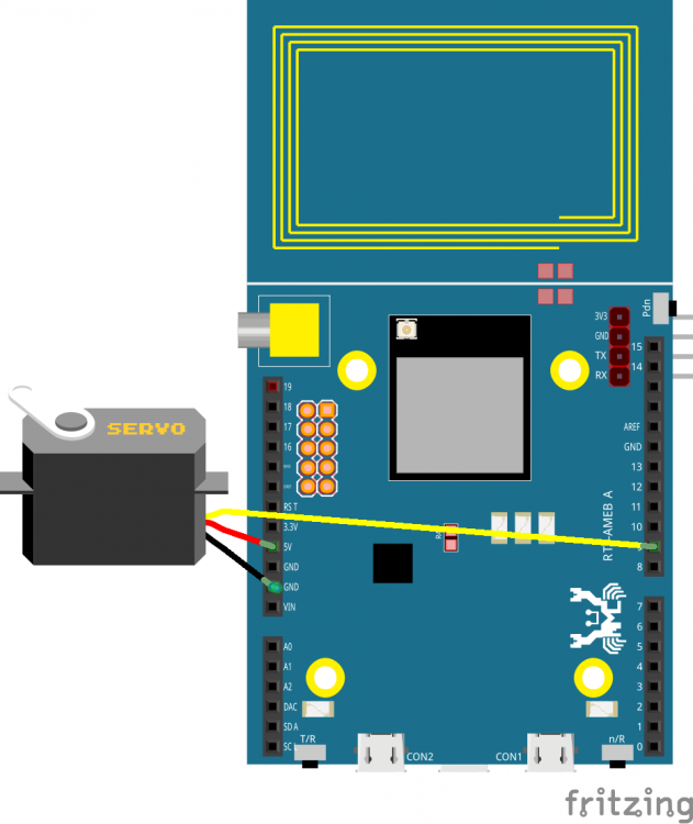
Cool
-
On 7/24/2020 at 11:10 PM, Danirov said:
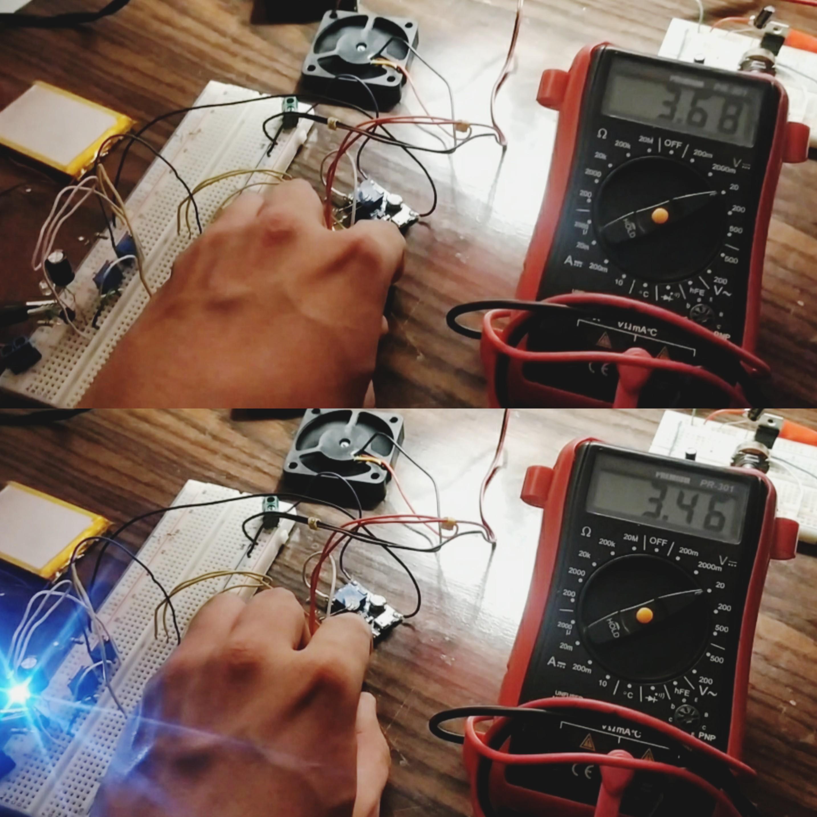
Hi everyone. Can you help me with this circuit I am working on, please?. (Image 1)
It consists of a TP4056 charger/controller connected to a 3.7v/1.4Ah Li-Ion battery to supply a low battery indicator and a load (3 leds + 2 fans) through a MT3608 Step Up to raise voltage from 3.7v to 9v. When the TP4056 is charging the battery through the USB port, the load is disconnected by the P-Mosfet.
PROBLEM: Voltage drops significantly when the load is connected.
Test1: Circuit without Debouncing/Load connected:
Voltage drops from 3.68v to 3.46v (image 2).
Low Battery Indicator: Blinks.Test2: Circuit with Debouncing/Load connected:
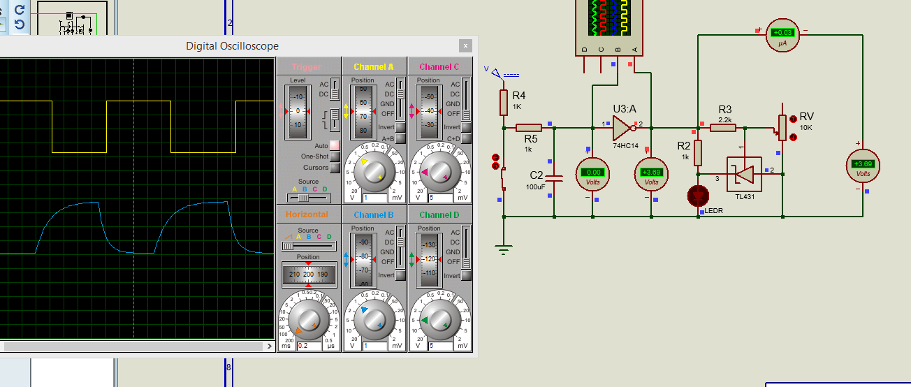
1) Debouncing Circuit: The voltage drops to 2.19v at the output of the Smichtt Trigger, therefore it isn't possible to energize the Step Up and the rest of the circuit.
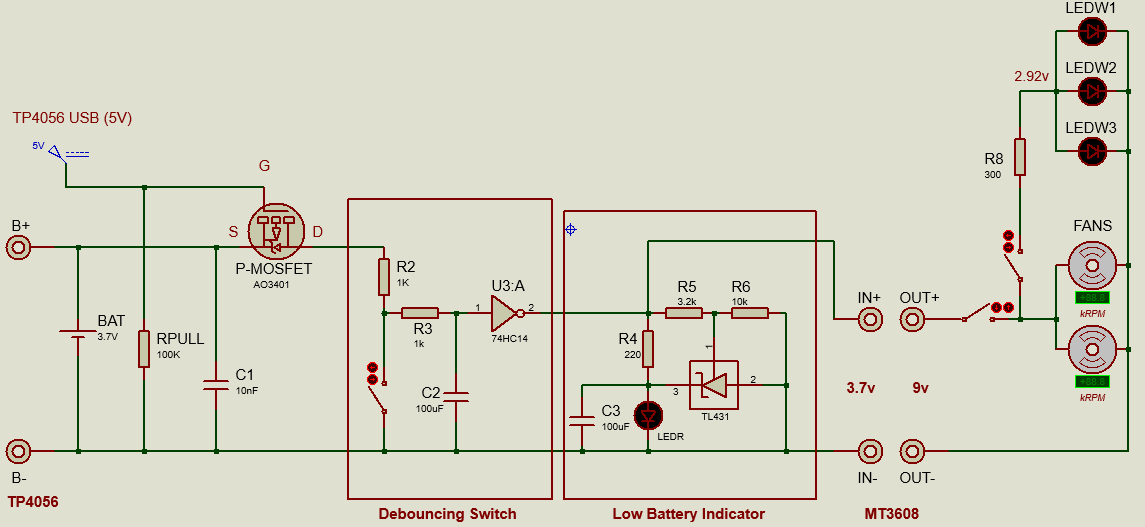
2) Low Battery Indicator: Blinks when switch is pressed.Test3: Circuit with Debouncing/Load disconnected:
1) Debouncing Circuit: Works fine (image 3).
2) Low Battery Indicator: Doesn't blink when the switch is turned ON/OFF.Is there something that I am forgetting to put in the circuit so the voltage is dropping?
I would suppose that the problem is at the DC/DC conversion of the Step Up, but everything is meeting its requirements (Vin:2v-24v/Imax: 2A).My system details:
Power consumption: 1.702W
Low Bat Indicator: (0.037W, 3.7v/0.01A)
Load: 2 Fans (1.44W, 9v/0.16A), 3 Leds (0.059W, 2.92v/0.02A).
Debouncing Circuit based on a Schmitt Trigger 74HC14 (Vin:2-6v/Vout:2-VCC, VCC and GND connected to battery line).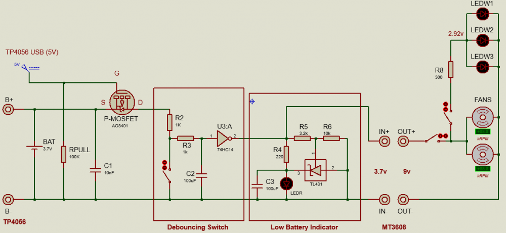


Wow, for the fans you need to draw more power externally or as mentioned above , build in a power enhancer (easiest way to implement a power transistor).
Design real time temperature monitoring
in Electronic Projects Design/Ideas
Posted
ADC_GetConversion(adc_channel_t channel): This routine is used to select desired channel for conversion and to get the analog to digital converted value.
CODE:
----------------------------------------------------
#include "mcc_generated_files/mcc.h"
#include "lcd.h"
#include "stdio.h"
/*
Main application
*/
// This function creates seconds delay.
// The argument specifies the delay time in seconds
void Delay_Seconds(unsigned char z)
{
unsigned char x,y;
for (y = 0; y < z; y++)
{
for (x = 0; x < 100; x++)__delay_ms(10);
}
}
//**************Declare Global Variables**************************************
uint16_t convertedValue = 0;
float voltage ;
char Buffer[20];
void main(void)
{
// Initialize the device
SYSTEM_Initialize();
// initialize the LCD
LCD_Initialize();
LCDPutCmd(LCD_CURSOR_OFF); //LCD Cursor off
LCDPutStr("ADC with MCC"); //Display String "ADC with MCC"
LCDGoto(0,1); //Go to second line
LCDPutStr("Turn POT on AN0"); //Display String "Turn Potentiometer on AN0"
Delay_Seconds(2); // 2 seconds delay
DisplayClr(); // Clear the display
while (1)
{
convertedValue = 0;
ADC_StartConversion(channel_AN0);
while(!ADC_IsConversionDone());
convertedValue = ADC_GetConversionResult();
voltage = (convertedValue * 5.0)/1023; // convert ADC count into voltage
LCDPutStr("Voltage = "); //Display "Voltage" on the screen
sprintf(Buffer, " %.3g", voltage ); // Convert voltage to string, rounded to 3 decimal points number
LCDPutStr(Buffer); //Display the Voltage on the screen
LCDPutStr(" "); // Clear after comma
LCDGoto(0,0); //Go to first line
}
}
/**
End of File
*/
--------------------------------------------------
Comment:
Instead of
voltage = (convertedValue * 5.0)/1023;
you can add your conversion equation of NTC sensor.
such as
temperature=B/(ln(convertedValue/r¤))
Here the convertedValue is the measured resistance of NTC.
B is the Beta value - need to be calculated.
ln is the natural logarithm.
r¤ is the reference resistance at a certain K temperature.