
Forlinx
-
Posts
65 -
Joined
-
Last visited
-
Days Won
1
Content Type
Profiles
Forums
Events
Everything posted by Forlinx
-
 Biochemical analyzer, abbreviated as bioanalyzer, primarily provides various clinical biochemical, hematological, and immunological testing projects for all levels of hospitals in the field of laboratory medicine. It is used to test clinical biochemistry indicators such as liver function, kidney function, blood lipids, diabetes, infection, rheumatology, and immunology. It provides important scientific evidence for the diagnosis, treatment, and prevention of diseases, and is an essential monitoring medical equipment in hospitals. Biochemical analyzers can be divided into fully automatic instruments and semi-automatic instruments, of which semi-automatic instruments are smaller in size, simple in structure, cheaper in price, and have higher application demand in the current market; fully automatic biochemical analyzers have less error in the results due to the analytical process without manual operation, and this type of instrument usually has an automatic report of abnormalities. It can automatically calibrate the working state, reducing the system error. According to the functional structure, the automatic biochemical analyzer is divided into an optical system, a constant temperature system, sample reaction stirring technology and probe technology, and a computer control part. With the enhanced performance of the ARM CPU-based, the computer control part of the automatic biochemistry analyzer has also started to switch to ARM Main Control Board to Folinx Embedded provide customers with Cortex-A53 platform master control Solution FETMX8MP-C industrial grade Computer on Module. The Computer on Module is based on NXP i.MX8M Plus processor development, with strong video processing capabilities and, a smooth operation experience, to help users develop powerful performance, beautiful interface devices. High performance: The CPU adopts 1.6GHz quad-core 64-bit Cortex-A53 architecture with a neural processing unit (NPU), offering a maximum operating speed of up to 2.3 TOPS. It comes with a standard configuration of 4GB DDR4 RAM + 16GB eMMC, providing sufficient hardware resources. Multiple Display Interfaces: CPU supports MIPI, LVDS and HDMI display natively, with the highest resolution up to 4K; Powerful Image recognition: Dual hardware ISP, resolution up to 12 MP, input rate up to 375M pixels/second, bringing significant improvement to the image effect; Abundant high-speed interface resources: 2 Gigabit Ethernet, 2 dual-purpose USB 3.0/2.0, 1 PCIe Gen 3, 2 SDIO 3.0, 2 CAN (including 1 CAN-FD), bringing more possibilities for high-speed signal transmission; Software equipped with: Linux5.4.70 and Andriod 10 operating system, the driver is perfect, and the system source code is open, giving you more support; Stable supply: full industrial design, full consideration of Medical application scenarios, 15 years + life cycle, free from your worries. Originally published at www.forlinx.net.
 -
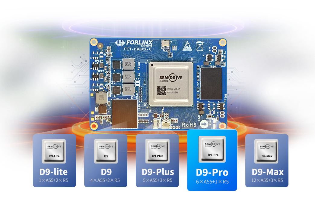
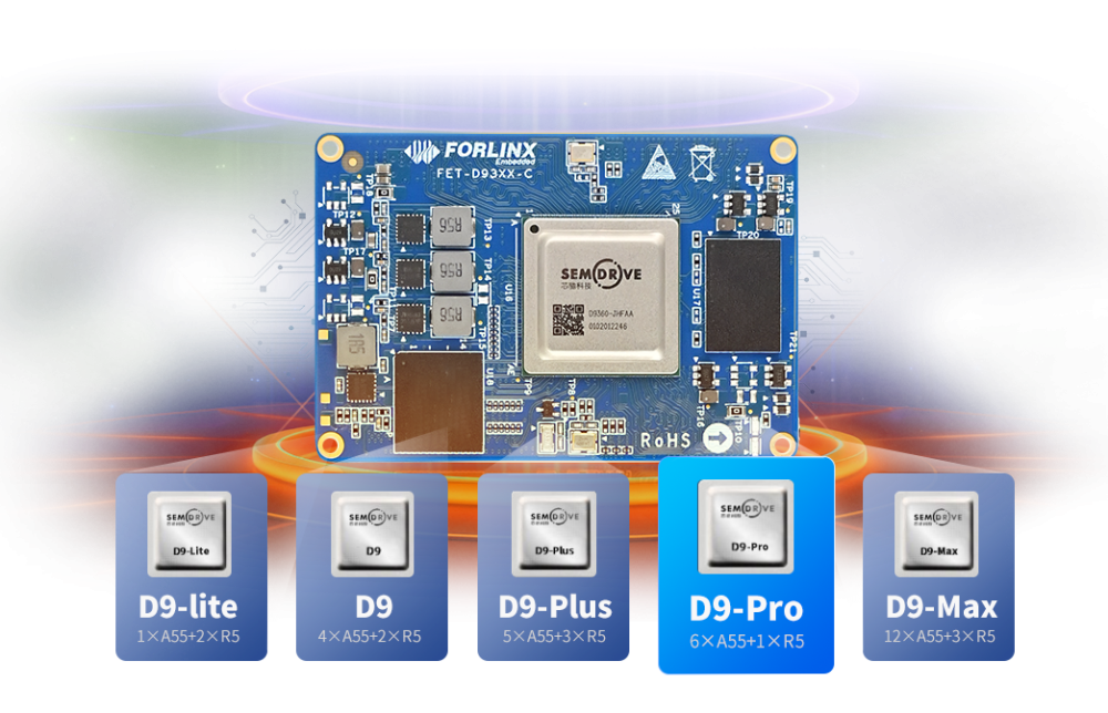
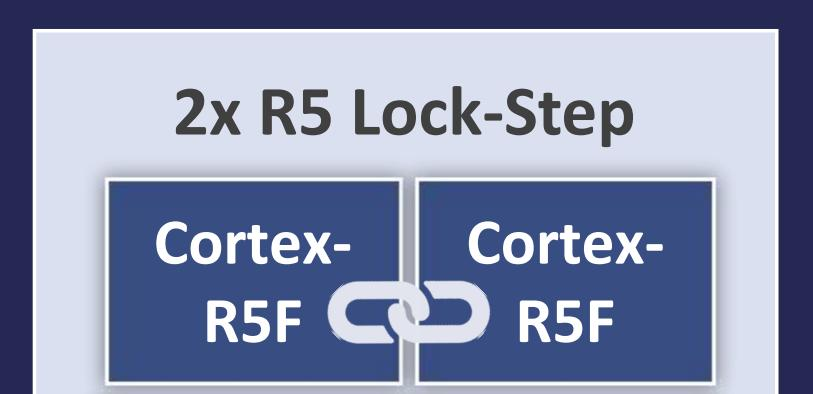
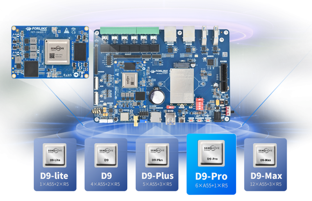
Forlinx Embedded and SemiDrive have teamed up to launch the FET-D9360-C System on Module(SoM), a high-performance industrial processor based on the D9-Pro processor. This SoM is designed to meet the growing demand for high-performance, reliable, and stable computing in the industrial sector. With six ARM Cortex-A55 high-performance cores and one ARM Cortex-R5 real-time core, it offers exceptional computing power and real-time processing capabilities. The D9360 SoM is compatible with multiple processors of the D9 series and is suitable for advanced industrial applications such as industrial IoT devices, industrial robots, and more. Originally published at www.forlinx.net.
-
01 Background In the process of rapid urban development, more and more pipelines are laid underground. How can such a large underground utility network be efficiently and accurately maintained? Given the complexity and potential hazards of underground utility networks, underground inspection robots have emerged as a practical solution. Indeed, it is possible to retrofit existing infrastructure with intelligent robot inspection and monitoring systems as well as disposal systems. By constructing a smart maintenance software platform, normal checks can be conducted on the fundamental attributes within the underground space to ensure the proper function of the facilities. The pipeline robot can be divided into three main components: robot operation, IoT sensing, and application. The robot operation part includes five main systems: cable subsystem, locomotion subsystem, power subsystem, communication subsystem, and positioning subsystem. These five subsystems are the basic guarantees that support the normal operation of the robot. The IoT sensing part includes various sensing methods such as image capture, sound capture, temperature and humidity capture, hazardous gas capture, and infrared thermal imaging. These sensing methods are important ways for the robot to perceive the underground space. The application part mainly involves processing the data collected by the IoT sensing part, including functions such as automatic warning subsystem, data analysis subsystem, remote management subsystem, etc. 02 Product features 1. Real-time detection and environmental monitoring: The robotic system is capable of monitoring the on-site environment in real-time, collecting information such as humidity, temperature, and harmful gas concentrations from the devices. It automatically analyzes whether these values exceed the alarm threshold and uploads the data. 2. Fully automated inspection: The robot conducts inspections based on preset schedules or through remote control via the cloud. Inspections can be categorized into two forms: routine daily tasks and special inspections. Special inspections refer to conducting inspections at specific locations designated by the cloud. 3. Automatic charging and low battery automatic return: The robot is capable of autonomously assessing the battery level and when it is low, it will automatically return to the charging station for recharging. 4. Autonomous obstacle avoidance function: The robot is equipped with sensors and is capable of automatically detecting obstacles in the track or pipeline environment during the inspection process. It will stop immediately and upload an alarm message if an obstacle is detected. 5.Inspection monitoring report: The robot will collect and process the inspection information it gathers, generating an inspection monitoring report that reflects the on-site conditions. 03 Product plan Based on the above features, we recommend the FETMX8MP-C System on Module as the core solution for the intelligent inspection robot for underground pipeline corridors to meet the customer's needs for machine vision and high-speed interfaces. Forlinx Embedded has launched the FETMX8MP-C SoM, which is based on the NXP i.MX 8M Plus processor. It not only sets a new benchmark for machine learning and vision but also makes an ideal choice for pipeline robot applications. In applications such as pipeline inspection, maintenance, and monitoring, the FETMX8MP-C has outstanding performance and versatile features. Smart Patrol: Equipped with a powerful Neural Processing Unit (NPU), the FETMX8MP-C enables intelligent analysis of pipeline conditions through machine learning, thereby improving inspection efficiency. High-definition images: With the advanced Image Signal Processor (ISP), the FETMX8MP-C produces high-definition images that assist pipeline robots in accurately identifying problems. Real-time video transmission: It supports video encoding and decoding, so that the pipeline robot can transmit video information inside the pipeline in real-time. Multi-communication interface: Rich communication interfaces, including USB3.0, PCIe3.0, SDIO3.0, CAN-FD, etc., enable the pipeline robot to flexibly respond to various connection needs. Some market research institutes predict that the global pipeline Robot Market scale will exceed 2 billion US dollars by 2025. With the continuous development of global urbanization and the continuous expansion of oil and gas pipeline construction, the market growth trend of pipeline robots is undoubtedly worth looking forward to. Indeed, the development of smart cities, artificial intelligence, and 5G networks will bring even greater market opportunities for pipeline robots. Originally published at www.forlinx.net.
-
T113-i: The Ideal Embedded Processor for Powerful Performance and Rich Interfaces The T113-i in the T113 family is a compelling, high-performance, low-cost embedded processor designed for a wide range of application needs. It integrates dual-core Cortex-A7CPU, 64-bit XuanTie C906 RISC-V CPU and HiFi4, which is impressive with excellent computing power. 1. Key Features: Support for full-format decoding: T113-i has excellent decoding capability and supports full-format decoding such as H.265, H.264, MPEG-1/2/4 and JPEG. Independent encoder allows efficient encoding using JPEG or MJPEG. Perfect video experience: It is integrated with H.265/H.264 decoding and SmartColor2.0 post-processing; T113-i offers users an unparalleled video entertainment experience, making every frame vivid and detailed. Seamless audio processing: With integrated ADCs/DACs and I2S/PCM/DMIC/OWA audio interfaces, T113-i can seamlessly collaborate with the CPU, accelerating multimedia algorithms and enhancing the user experience. Diverse display outputs: To meet various screen display requirements, T113-i supports RGB/LVDS/MIPI DSI/CVBS OUT display output interfaces, easily adapting to different application scenarios. Extensive connectivity: T113-i offers a wide range of connectivity interfaces, such as USB, SDIO, EMAC, TWI, UART,SPIPWM, GPADC, LRADC, TPADC, and IR TX&RX, enabling seamless connections with various devices. 2. T113-i Application Processor Block Diagram Allwinner T113-i vs T113-S3 Differences and Options T113-i and T113-S3 in T113 series have attracted considerable attention in terms of popularity. However, there are significant differences between the two models, making one model more suitable for specific application environments than the other. So what's the difference between the T113-i and the T113-S3? Which processor with different suffix models is more suitable for industrial scenarios? 1. Differences between T113-i and T113-S3: Operating temperature standard T113-i can operate at true industrial temperature (-40 ℃ ~ + 85 ℃) without heat sink; T113-S3 has a small working temperature range (-25 ℃ ~ + 75 ℃) without heat sink. Support large capacity DDR T113-i supports 128/256/512M Byte multiple industrial capacity DDR3, up to 2GByte; The T113-S3 is fixed to 128MByte on-chip memory and does not support expansion. Built-in RISC-V slave core The T113-i has a built-in high-performance, high real-time RISC-V slave core. T113-S3 has no RISC-V core, only ARM+DSP cores. Different packaging T113-i is LFPGA. T113-S3 is TQFP. 2. Considering these differences, how to choose between the T113-i and the T113-S3? If your application scenario is industrial grade or has severe temperature control requirements, then the T113-i would be a better choice as it has a wider operating temperature range to better meet these needs. In addition, the T113-i supports high-capacity DDR, which is an advantage for industrial applications that need to process large amounts of data. Finally, the T113-i's built-in RISC-V slave core may provide an additional advantage for certain applications that require high performance and high real-time performance. If your application scenario is commercial grade and you don't have special temperature control requirements, then the T113-S3 can also be considered. However, even with the addition of a heat sink, it cannot reach true industrial-grade temperatures. In addition, the T113-S3's memory is fixed and does not support expansion, which may limit its use in certain business applications. Industrial-grade SoM FET113i-S based on T113-i FET113i-S SoM is developed and designed based on the T113-i industrial-grade processor released by Allwinner. The T113-i runs at 1.2GHz and integrates a dual-core Cortex-A7 CPU, a 64-bit XuanTie C906 RISC-V CPU, and a DSP to ensure excellent computing power; it not only supports various formats of video decoding and a variety of encoding, but also has a variety of audio interfaces and display interfaces to meet the various needs of multimedia applications. In addition, the T113-i processor has a wide range of connectivity interfaces, including USB, SDIO, UART, SPl, CAN, and Ethernet. 1. Product features: Real industrial processor, operating temperature -40 ℃ ~ + 85 ℃; Available in 256MB and 512MB memory capacity configuration options; With the multi-core heterogeneous architecture of ARM+RISC-V+DSP, it can easily handle various complex scenario requirements; Powerful video encoding and decoding capabilities, suitable for various multimedia application scenarios; Pre-installed with the 5.4.61 operating system, supports system flashing via TF card and USB OTG. 2. Product appearance and size: 3. Product data list: Linux 5.4.61 information, user manual, compilation guide,Linux kernelsource code, file system, factory image, SD flash card making tool, USB OTG flashing tool, Qt test routine source code,Application note* Hardware documentation list, including hardware manual, carrier board schematic source files (in AD format), carrier board PCB source files (in AD format), carrier board schematic PDF, chip data sheets, SoM 2D CAD drawing, carrier board 2D CAD drawing, pin no., pin multiplexing table, design guidance*.*: Continuously provide and enrich documentation after product release. 4. OK113i-S Development Board Overall Power Consumption Table We provide a detailed power consumption test report for your reference. The following is the power consumption table of the whole machine under the Linux system Test Items SoM Power(W) Development Board Power (Including SoM)(W) No-load starting peak power 3.25 9.01 No-load standby power 0.4 1.24 CPU stress + memory + eMMC read/write stress test 1.05 1.89 7-inch LCD screen + 4G + U disk + video decoding 0.7 3.82 7-inch LCD + 4G + U disk + video encoding 0.75 3.75 Note: 1. Test conditions: the SoM configuration is 512MB RAM + 8GB eMMC,4G module Quectel EC20, and the screen is anFolinxoptional product. The SoM is powered by 5V; the carrier board is powered by 12V, and the system is a Linux system. 2. Power consumption is for reference only. TI13-i SoM Carrier Board Hardware Design Introduction The FET113i-S SoM features a highly integrated design, with power, resetcircuit, and memory circuits integrated into a compact module. This makes the external circuitry very simple, requiring only a 5V power supply and a reset button to form a minimal system. As shown in the figure below: Of course, in practical applications, we usually need to connect external devices, such as debugging serial ports and USB interfaces, to perform system flashing and view debugging information. Forlinx provides a detailed default interface definition for the SoM, which allows you to easily add the required functions based on it. 1. Minimum System Schematic The schematic diagram of the minimum system has been provided and the above diagram is only a schematic for your reference. Note that the source file schematic contains specific connections. To ensure the normal operation of the core board, in addition to the power supply VSYS_5V, it also requires a CPU_RST button, an OTG or SD card interface, and a UART0 debugging serial port circuit. These components not only facilitate system flashing and booting but also facilitate debugging and verifying the operational status of the system. 2. Carrier board Hardware Design Guide Power supply requirements PIN3, PIN4, VCC-5V-SYS Please ensure that the SoM is continuously powered and the current is not less than 1A. The power supply of PIN2, VCC-3V3 SoM to the carrier board shall not exceed 0.5A, which is only used for timing control and SD card power supply. Reset Signal PIN146, CPU-RST-KEY is the reset key interface. Resistor and capacitor loads shall not be added to the carrier board to avoid affecting the normal startup of the SoM. If not in use, it can be left floating. Electricity levelMatching issues The PE groups are all 1.8 V levels, so note the level matching. Signal pins that are not used by the SoM can be left floating, but be sure to connect all GND. Power-up sequence It is strongly recommended that users refer to the design of the development board when designing the carrier board.Please use the VDD_3V3 output from the SoM as the enable for powering up the carrier board and strictly control the power-up timing. Incorrect power-up timing may result in excessive current during the power-up phase, failure of the device to boot, or irreversible damage to the processor. IO leakage problem If there is a high level sink current on the signal pin of the SoM, it may cause the SoM to leak electricity. The most typical case is a serial port leakage. In order to avoid this kind of problem, the carrier board adopts the anti-leakage design at the debugging serial port. If the custom-made carrier board also encounters such a situation, it can be handled by referring to development board design. Originally published at www.forlinx.net.
-
Energy Management System(EMS for short) is designed and implemented specifically for energy storage systems, which plays a vital role in the field of new energy storage systems. EMS can help enterprises or institutions achieve efficient, safe, and reliable management of energy storage equipment, optimize energy storage and release, reduce costs, and improve energy efficiency. To achieve these functions, EMS also needs to rely on various systems. This paper will analyze in detail the application of embedded system in EMS and its close relationship with it. 01 Embedded Linux System Purpose: It is often used in the monitoring system of energy storage power station as the background support of EMS to ensure the real-time processing and response of large-scale data of energy storage system. Features: It can be customized according to the specific needs of EMS, providing stable and reliable data processing and communication capabilities to ensure the efficient operation and monitoring of the energy storage system. Note: Tailoring and customization is required to accommodate specific EMS needs. 02 Microcontrollers Purpose: It is used in small energy storage devices or distributed energy storage systems to monitor and control the charging and discharging process of a single energy storage unit. Features: Through real-time data acquisition and upload, the micro controller can provide accurate charging and discharging data and status information for the EMS, and then realize the intelligent adjustment of the energy storage strategy. Note: The computing power and storage capacity are limited and not suitable for complex EMS tasks. 03 Programmable Logic Controller (PLC) Application: In large-scale energy storage power stations and industrial energy storage applications, PLC works closely with EMS to ensure safety control and optimization during energy storage. Features: The stability and real-time performance of PLC provide reliable data acquisition and control interface for EMS, so that the energy storage system can accurately respond to dispatching instructions and ensure the stable operation of the system. Note: The source code is usually not open, and the customization is poor. 04 Embedded SOC (System Chip) Purpose: In high-end EMS equipment, as the core processing unit, to ensure the rapid processing and analysis of energy data. Features: Its high performance and low power consumption meet the dual requirements of EMS for data processing speed and energy efficiency. Note: The design is complex and requires specialized development tools and teams. 05 Internet of Things (IoT) Device(IoT Devices) Purpose: As a remote monitoring and management means of EMS, the Internet of Things equipment realizes wireless monitoring and data acquisition of distributed energy storage equipment. Features: IOT equipment provides convenient data transmission and remote management channels for EMS, and helps to realize remote monitoring, fault diagnosis and other functions of energy storage system. Note: Data security and stability need to be considered. Summary In EMS, the selection of an appropriate embedded system involves a trade-off of multiple factors, including but not limited to system complexity, real-time requirements, cost, and development cycle. It is critical to select the right embedded system for the specific needs of the EMS, which will directly affect the performance, stability, and economic benefits of the energy storage system. To ensure the successful implementation and operation of an EMS, it is wise to seek the support and assistance of a specialized energy management and automation system provider. FCU2601 embedded Control Units is Folinx Embedded an EMS energy control unit product designed for the lithium battery energy storage industry, which is designed with high performance, multi-interface and low power consumption, and widely meets the local energy management application requirements of various energy storage systems. The FCU2601 embedded control unit takes into account the differentiated needs of different scenarios in the energy storage industry, and makes full preparations in hardware, protection, certification, software and other aspects to ensure the applicability, stability and reliability of the product. Originally published at www.forlinx.net.
-
Traditional storage lockers often require coins, paper barcodes, or scanning mobile QR codes, and so on, which are inconvenient, prone to low operational efficiency, and have risks such as lost or damaged unlocking credentials. In order to effectively solve these problems, smart face recognition storage lockers have emerged. The smart face recognition storage locker solution utilizes facial recognition technology, replacing traditional paper notes, keys, or cards with the user's face as the credential for opening the locker. When using the storage locker, users can register their facial information into the system by selecting the "store" option and having their face captured. When picking up things, you can open the locker to store things via facial recognition, saving your time for keeping notes and cards. At the same time, the smart face recognition storage lockers in scenic areas can record and analyze customer storage and picking up records in the background, providing convenience for locker administrators to understand the usage status of the storage lockers. As the core component of a smart face recognition storage locker, the controller needs to have the following functions: Multi-mode recognition: The controller should support various recognition modes, such as face recognition, fingerprint recognition, IC card recognition, etc., to meet the needs of different users and provide more flexible identity verification methods. High-performance processor: Equipped with high-performance processors to ensure the response speed and processing capacity of the system, to adapt to large-scale users and high-frequency access scenarios. Network connectivity and cloud services: It has the ability of network connection, supports communication with cloud services, and realizes remote monitoring, management, data synchronization and other functions. Safety guarantee: It emphasizes the security of user data and uses encryption algorithms and other technical means to prevent information leakage and illegal access. Open interface: It provides rich interfaces for easy integration with other hardware devices, such as door magnets, electric locks, sensors, etc., to realize a more complete access control or security system. Forlinx has launched the FETMX8MP-C System on Module(SoM) as the main control scheme of the control cabinet.This platform is developed and designed based on the NXP i.MX 8M Plus processor. This family of processors focuses on machine learning and vision, advanced multimedia, and industrial platforms with high reliability. Human-machine interaction: The FETMX8MP-C SoM can support 4K display output at most, and can support three display interfaces and three different displays; Rich peripheral interfaces: With rich interfaces, it supports integration with other hardware devices, such as door magnets, electric locks, sensors, etc., to build a complete access control or security system. Face acquisition: Built-in image signal processor (ISP) and two camera inputs can efficiently and accurately identify and verify the user's identity. AI capability: with neural processing unit (NPU), the maximum running rate can reach 2.3 TOPS, which can match advanced face recognition algorithms; Originally published at www.forlinx.net.
-
Traditional weed removal methods include manual weeding, mechanical weeding, physical weeding, chemical weeding, etc. However, these methods are either inefficient with high labor costs, or they fail to completely remove weeds, leading to environmental pollution and residual chemical substances that can be absorbed by the soil, thereby affecting subsequent plant production. Excessive use of herbicides, with glyphosate being the main component, poses significant risks as it can enter the bodies of animals through contaminated food and water. The use of mechanical weeding can disrupt soil structure and ecological balance. On the other hand, manual weeding is time-consuming, laborious, and costly. In recent years, there has been a growing demand for intelligent living, and with the maturity of machine vision technology, cameras can be used to capture images and identify weeds, enabling selective weed removal. As a result, the use of herbicides can be reduced or eliminated. In the field of agriculture, smart weeding robots are gradually emerging as a promising solution. The most crucial step in the crop and weed detection process for a weeding robot is accurately differentiating between crop plants and weeds. It is indeed not an easy task to differentiate between crops and weeds due to the wide variety and irregular distribution of weeds, as well as the similarities in physical characteristics between crops and weeds. If we want an artificial intelligence system to determine whether to remove an object (weed) from the ground, it needs more than just the ability to recognize the object optically. It also needs the capability to differentiate whether the object is a weed or a crop. Weeds and crops typically have different spectral characteristics, which is why multi-spectral cameras can help in accurately classifying them by ensuring that the optical sensors capture images that enable proper differentiation. This capability can assist the system in successfully removing weeds. Features of smart weeding robots include: Efficient intelligence: Equipped with advanced image recognition technology, smart weeding robots can accurately identify weeds and crops, achieving precise weeding operations and improving work efficiency. Autonomous navigation: Equipped with advanced navigation systems, smart weeding robots can autonomously plan work paths, adapt to different shapes and sizes of farmland, and provide comprehensive coverage to ensure thorough weed removal. Environmentally friendly and efficient: Powered by batteries, zero emissions, environmentally friendly. By adopting intelligent weeding technologies such as lasers, the use of chemical herbicides is reduced, resulting in lower residue levels in agricultural products. Autonomous decision-making and learning: Algorithms with autonomous decision-making capabilities enable robots to respond adaptively to new situations. Machine learning techniques can be used to improve recognition and decision-making capabilities. To better meet the high-performance requirements of intelligent weeding robots, Forlinx Embedded has launched FET3588J-C platform, which has the following characteristics: High performance and low power consumption: The FET3588J-C quad-core Cortex-A76 runs at up to 2.4GHz to support high-load operation, while the quad-core Cortex-A55 is suitable for low-power operation at low-load operation, balancing performance and power efficiency. Advanced image processing: The FET3588J-C introduces a new generation of 48-megapixel ISP3.0, which enables lens shading correction, 2D/3D noise reduction, sharpening and de-fogging, fisheye correction, gamma correction, and wide dynamic contrast enhancement, which dramatically improves the quality of robotic image capture. Rich interface resources: It has abundant interface resources to meet the access needs of robots to various sensors. More access to sensors helps devices to more fully capture environmental data. The platform can also access external storage interfaces such as SATA3.0 and USB3.0 so that data can be stored locally, and it also supports wireless communication methods such as WiFi, 4G, and 5G, which makes it convenient for users to query device information on the mobile side. The rich functions enable the robot to perceive and understand the surrounding environment more comprehensively. Powerful AI computing power: It has a built-in NPU with a computing power of 6 TOPS, which provides powerful AI learning and edge computing capabilities for robots to cope with different work scenarios more intelligently. Extreme stability and performance support: The SoM of the platform has undergone rigorous environmental temperature testing and stress testing, providing extreme performance support and stable operation guarantee for high-end applications, ensuring that the intelligent weeding robot can perform well in various complex environments. With the continuous upgrading of intelligent hardware, intelligent weeding robot has become an important technology in modern agriculture. As its core engine, Forlinx's Embedded FET3588J-C platform provides more powerful support for the development of intelligent weeding robots, and brings more efficient and intelligent solutions for weeding robots. Originally published at www.forlinx.net.
-
The Food and Agriculture Organization (FAO) of the United Nations released an assessment report on October 13th, regarding the impact of disasters on global agricultural production and food security. The report states that disaster events have caused a loss of approximately $3.8 trillion in crop and livestock production over the past 30 years. The FAO stated that this report, titled "The Impact of Disasters on Agriculture and Food Security," is the first global assessment conducted by the organization on how disasters affect agricultural production. The report reveals the significant impact of meteorological disasters on global agricultural production. The report indicates that meteorological factors are currently one of the most serious threats to agriculture, and extreme weather events and climate change have brought great uncertainty to agriculture. To better monitor and understand the impact of meteorological factors on agriculture, agricultural meteorological monitoring instruments have emerged. Agricultural meteorological monitoring instruments are advanced devices that offer various functional advantages and provide comprehensive meteorological monitoring services for agricultural production. Agricultural meteorological instruments can measure many meteorological data, including temperature, humidity, air pressure, precipitation, wind speed, and wind direction to monitor environmental changes and help farmers better plan the planting and harvest of crops. In addition, Agrometeorological stationregular monitoring of meteorological factors during the crop growth process helps to understand their impact on crops. This allows for appropriate water and fertilizer management, as well as the ability to predict and prevent disasters. Agrometeorology monitor Agricultural meteorological instruments can provide accurate weather forecasts and warning information by monitoring real-time weather conditions and analyzing data. This allows for adjustment of crop planting and fertilization timing, improved yield and crop quality, and prevention or mitigation of crop loss. Mitigating the impact of disasters on crops and agricultural production helps to improve the economic benefits and quality of life for farmers. Forlinx Embedded provides NXP's i.MX9352 platform - FETMX9352-C industrial-grade SoM for agricultural meteorological detectors. The product undergoes strict stability testing to ensure hardware and system stability in various harsh environments in different regions. Features of the scheme: High performance: integrated 2 Cortex-A55 cores + 1 Cortex-M33 real-time core, main frequency: 1.7 GHZ Integrated NPU: Meeting AI Edge Computing Needs Network communication: support 2-lane gigabit network, support 4G, Bluetooth and other wireless communication modes, select wired and wireless transmission modes according to the environment, and upload the collected data to the server. Support 8-lane serial port: can be connected to a variety of sensor devices, such as: temperature, humidity, wind, rainfall, etc. Support SPI: expandable analog ADC, 24-bit accuracy Support SD card: can be used for local storage Agrometeorological monitoring instrument plays a very important role in the field of agriculture.The growth and development of crops can not be separated from meteorological conditions and agrometeorology monitor. The construction of the instrument is helpful to grasp and monitor the changes of meteorological conditions in the process of crop planting, predict and prevent possible meteorological disasters, and provide decision-making suggestions and scientific basis and technical support for farmers. Originally published at www.forlinx.net.
-
The OK7110-C's screen timing requires the dedicated calculation tool starFive_DSI_Tool.exe, which is stored in the Tools/dsi_tool folder of the user profile. Operation methods: 01 Parameter configuration Modify the input.ini file, which is used to configure the screen parameters; the following are the specific configuration parameters: hactive: Effective screen length Vactive:Effective screen width Bpp:bit per pixel Pixel depth fps:frame per second Frame rate pixelclock_source:Pixel clock source. Because pixel clock is divided by JH7110 PLL2 integer frequency, here need to input PLL2 frequency; VF2 is 1188MHz. dlanes: mipi dsi Number of channels ref_pixclk:reference pixel clock reference pixel clock; according to the screen datasheet to know its reference pixel clock or reference pixel clock range.If it is a range, it is better to write the low bound here; this parameter can be filled with 0 to indicate that the reference clock is not used in the calculation or needs to calculate the timing of other frame rates. nr_timing_generated:Number of time series to be generated For example 02 Running You need to install git on Windows.Open the DSI _ tool directory with git bash Run the script run. Sh. #!/bin/bash output=$1 if [ "$output" == "" ]; then output=output.txt fi ./StarFive_DSI_Tool.exe < input.ini > $output Use the command./run. Sh. Use the command./run. Sh. The timing generated by the tool is calculated from input.ini. For example: Welcome to use StarFive DSI timing generation tool v1.0 { .dpi_timing = { //1024x600, 24 bits, 49.93 Hz .pixelclock = 49500000, .hactive = 1024 , .hfront_porch = 475 , .hback_porch = 5 , .hsync_len = 5 , .vactive = 600 , .vfront_porch = 47 , .vback_porch = 5 , .vsync_len = 5 , }, .dsi_timing = { .dlanes = 4 , .bitrate = 380000000, .hsa = 910 , .hbp = 908 , .hfp = 902 , .hact = 3072 , }, }, The number of generated timings is determined by the nr_timing_generated parameter in input.ini. Note that if output.txt is generated in multiple groups,not every group will work properly. It is necessary to try them one by one to select the right timing for the screen. Timing example: { .dpi_timing = { //1024x600, 24 bits, 49.93 Hz .pixelclock = 49500000, .hactive = 1024 , .hfront_porch = 475 , .hback_porch = 5 , .hsync_len = 5 , .vactive = 600 , .vfront_porch = 47 , .vback_porch = 5 , .vsync_len = 5 , }, .dsi_timing = { .dlanes = 4 , .bitrate = 380000000, .hsa = 910 , .hbp = 908 , .hfp = 902 , .hact = 3072 , }, Make changes against the device tree file OK7110-C.dts: 1. Modify the seeed_plane point: dlanes: Modify according to the number of channels used on the screen. width-mm,height-mm,data-mapping:Modify according to the actual information on the screen. 2. Modify mipi_dsi node: Bitrate,hsa,hbp,hfp;modify according to the corresponding values in generation_timing.dsi_timing 3. panel-timing: The data in panel-timing, hactive and vactive are filled in according to the actual value of the screen; the rest of the panel-timing is modified according to the corresponding content in the generation sequence.dpi_timing. panel-timing. The modifications are as follows: panel-timing { clock-frequency =; hactive =; vactive =; hsync-len =; hfront-porch =; hback-porch =; vfront-porch =; vback-porch =; vsync-len =; }; After the modification, burn the new device tree into the device and see if it can be displayed properly. If it can't be displayed normally, use the rest of the timings in output.txt and continue to try according to the above steps; if it can be displayed normally, the screen adaptation is completed. Originally published at www.forlinx.net.
-
Amazon recently announced its plan to use drones to deliver packages in the UK by the end of 2024. Amazon has been investing in drone technology for a decade now, but currently, its drone delivery services are limited to a few regions and primarily cover the delivery of non-pharmacy products such as home goods, office supplies, and beauty products. To drive business growth, Amazon has decided to expand its drone delivery services to the pharmaceutical industry. After purchasing medication from Amazon Pharmacy, users will be able to receive fast delivery within 60 minutes through drone services. This initiative aims to meet consumer demand for rapid medication delivery, which is particularly important in emergency situations. To drive business growth, Amazon has decided to expand its medication delivery services to the pharmaceutical industry. The launch of drone delivery services will bring new growth opportunities to the e-commerce industry and foster further advancements in technology innovation and the drone industry, opening up new possibilities for future delivery methods. Absolutely, in addition to that, we can also expect to see more drones playing a role in other industries, such as agriculture, mapping, and more. Indeed, the development of drone technology undoubtedly brings forth more possibilities for both our personal lives and work environments. However, drone product design faces certain challenges. For the purpose of targeted application in various scenarios, many drones adopt a modular design, which means incorporating additional expansion modules beyond the basic flight control system to achieve different functionalities. While this design approach offers flexibility, it increases the overall weight of the drone to some extent. As a result, the size of the drone is limited. If the size is too small, it may not be able to accommodate the necessary expansion modules. On the other hand, if the size is too large, it can increase power consumption and reduce battery life, affecting the overall flight endurance of the drone. Debugging and adaptation can also be a complex process. For drone product design and development, using a highly integrated processor with more advanced features as the drone's main controller is a more suitable choice. This allows for the integration of required functionalities directly into the drone, tailored to meet the specific needs of different fields. In this way, it is possible to better control the size of the drone, while balancing performance, size, and endurance. Forlinx Embedded recommends using the FET3588-C SoM as the main controller for a highly integrated drone. Forlinx Embedded's FET3588-C SoM is developed and designed based on Rockchip's RK3588 processor. It integrates a quad-core Cortex-A76 and quad-core Cortex-A55 architecture. The A76 cores have a clock speed of up to 2.4GHz, while the A55 cores have a clock speed of up to 1.8GHz, providing powerful performance support. The FET3588-C SoM has also undergone rigorous testing to ensure stability and reliability for customers' high-end applications. In terms of the most fundamental shooting functions of drones, the Forlinx Embedded FET3588-C SoM is also highly capable. It introduces the new generation 48 million pixels ISP3.0, which allows for lens shading correction, 2D/3D noise reduction, sharpening and fog removal, fisheye correction, gamma correction, and wide dynamic contrast enhancement effects. These features significantly enhance the image quality and are suitable for customers with special image requirements. RK3588 has undergone significant improvements in integer operations, floating-point operations, memory, overall performance, power consumption, and core area. It also features a wide range of high-speed data communication interfaces, meeting the diverse needs of various industries. Additionally, it is equipped with Rockchip's self-developed tri-core NPU, which can work in collaboration or independently, allowing for flexible allocation of computational power and avoiding redundancy. The integrated NPU can deliver up to 6 TOPS of computing power, empowering artificial intelligence applications and providing more possibilities for expanding the application scenarios of drones. Drones have penetrated into numerous industries, and the increasingly fierce competition has driven drones to develop and improve in the directions of intelligence, miniaturization, and systematization. In the selection of drone controllers, there will also be a greater preference for more versatile, all-encompassing, and powerful platform. The above is the drone controller selection scheme recommended by Forlinx Embedded, based on the FET3588-C SoM. We hope this can be helpful to all engineers.
-
This solution employs Lontium Semiconductor's LT8912B, which features a single MIPI D-PHY receiver with four data lanes, each running at speeds of 80Mbps to 1.5Gbps, with a maximum input bandwidth of 6Gbps. LVDS has 1 clock lane and 4 data lanes for a maximum of 1.0 Gbps per data lane. The HDMI output supports the HDMI 1.4 standard, allowing for a maximum output of 60Hz at 1080p resolution with 8-bit color depth. The LT8912B does not support DDC and HDCP. This article describes how to use LT8912B to convert MIPI to LVDS. The hardware implementation can involve directly designing the LT8912B chip onto the carrier board or designing an adapter board to connect LT812B to the OK7110-C development board. Software modification method: Create a script file test. Sh to write the register parameters of I2C of LT8912B chip (the parameter configuration in this article is based on an LVDS screen with single 8-lane, 1280X800 resolution, and GT928 touch chip, and the specific parameter configuration is mainly based on the actual screen parameters). Place the test.sh script under /usr/bin/, or you can modify the name as you wish. Then, modify the path in the service configuration file. vi /usr/lib/systemd/system/[email protected] Note that a row has been addedExecStartPost=/usr/bin/test.sh & Note that if the path is modified, the path in the added line needs to be matched /usr/bin/test.sh [Service] Type=oneshot RemainAfterExit=yes ExecStart=/usr/lib/systemd/systemd-fsck %f ExecStartPost=/usr/bin/test.sh & TimeoutSec=0 Modify the device tree OK7110-C.dts Originally published at www.forlinx.net.
-
There are several methods to configure the Linux kernel, and one of them is using the text menu-based configuration interface called "make menuconfig", which provides an intuitive and straightforward way of configuring the kernel. 1. Components of the Linux Kernel Configuration: Configuring the Linux kernel involves three main components: a Makefile, a configuration file, and a configuration tool. In this article, we will dive into a specific configuration tool called make menuconfig. 2. The process of using make menuconfig: When you execute make menuconfig, several files are involved: • "scripts" directory in Linux root folder (not relevant for end users) • Kconfig files in the arch/ $ARCH/directory and various subdirectories • Makefile file that defines the values of environment variables • .config file to save the default system configuration values • The include/generated/autoconf.h file, which stores configuration options as macro definitions 3. How to add kernel functions using make menuconfig To illustrate the process, let's consider adding new functionality to the kernel using make menuconfig: Step 1: Add the appropriate options to the Kconfig file using the Kconfig syntax. Step 2: Execute make menuconfig to generate the .config and autoconf.h files. Step 3: Add compilation options to the relevant makefile. Step 4: Execute make zImage to compile the kernel with the new features. With the above steps, you can effectively use make menuconfig to configure the Linux kernel. Originally published at www.forlinx.net.
-
On November 7th, 2023, Forlinx Embedded launched the Debian 11 system for the first time on their development board, OK3568-C/OK3568J-C, which is based on the RK3568 chipset. Forlinx Embedded officially supports the Debian 11 system on the OK3568-C/OK3568J-C platform. In the field of embedded development, stability and richness are crucial factors. The RK3568, as Forlinx's flagship embedded product, has high performance, low power consumption, and rich interface functions, making it appreciated by industry users. Debian 11 is a stable, reliable, and open-source operating system, which provides a powerful foundation for the OK3568-C. Debian 11 has undergone rigorous testing and validation to ensure system stability, so there is no need to worry about unexpected crashes or data loss. Moreover, Debian 11 has a vast software library, which enables developers to easily install and update required software packages. By combining the advantages of the OK3568-C hardware with Debian 11, developers can fully leverage the diversity of the 3568 hardware interfaces while enjoying the stability and open-source nature of Debian 11. Indeed, this strong combination provides an ideal environment for various embedded projects. When it comes to stability, free and open source, versatility, and vast software libraries, no operating system can rival Debian. Debian is a truly free operating system, and its strength is not only reflected in technology, but also in its active community. Stable Value: Debian stands out for its world-renowned stability. Whether you are building critical business systems or looking for reliable daily desktops, Debian is always the best choice. Debian 11 has undergone rigorous testing and validation to ensure system stability, so there is no need to worry about unexpected crashes or data loss. Free and Open Source: Debian adheres to the concept of free and open source, allowing you to freely use, modify, and share it. This is a truly free operating system. Not only can Debian be obtained for free, but you can also freely view, edit, and distribute its source code. Huge Software Library: Debian has a vast and diverse software library that covers almost any application and tool you can imagine. From office software to entertainment applications, server services to programming tools, Debian has everything in its software library. Not only that, it also provides an easy-to-use package management system, allowing you to easily install and update software. Multi-architecture Support: Debian supports multiple hardware architectures, including x86, ARM, PowerPC, MIPS, etc., making it suitable for various devices and systems. Whether you use a desktop, laptop, server, or embedded device, Debian can provide the ideal solution. Active Community Support: The Debian community is a vibrant place where you can find help, advice, and resources. Both novice and experienced users can participate in the community and receive support. Originally published at www.forlinx.net.
-
On November 1, 2023, Vision China Shenzhen, hosted by the China Machine Vision Industry Union (CMVU) and organized by Munich Exhibition (Shanghai) Co., Ltd., successfully concluded at Hall 7 of Shenzhen International Convention and Exhibition Center (Bao'an New Hall). As an annual high-end industry exhibition targeting international vendors, Vision China is dedicated to advancing machine vision technology and its application integration, empowering industrial automation. The exhibition brought together renowned machine vision vendors, experts, scholars, and buyer groups from both domestic and international markets. With a global perspective, it showcased high-quality products and innovative technologies in the machine vision industry, earning recognition from numerous exhibitors and visitors. The three-day exhibition attracted more than 180 domestic and international high-tech companies, with an exhibition area of nearly 20,000 square meters. During the exhibition, the number of visitors exceeded 35,000. The market space for the transformation of China's intelligent manufacturing equipment industry structure and technological advancement is enormous, and the machine vision industry will benefit from it. Currently, China is further deepening the adjustment of industrial structure, promoting technological innovation in the manufacturing industry, and advancing the level of intelligent manufacturing. VisionChina Shenzhen provides a professional exhibition platform, focusing on the transition from technology-driven to innovation-driven, and dedicated to facilitating the transformation and upgrading of the industrial structure as well as further intelligentization of the manufacturing industry. The participating companies in the exhibition showcase over 50 new products and solutions. These include intelligent cameras, image processing systems, integrated machine vision systems, circuit boards, industrial lenses, and other primary and auxiliary components of machine vision. The extensive display of new products also demonstrates that Chinese machine vision manufacturers embrace an open attitude towards compatibility with new ecosystems, and empower intelligent manufacturing with cutting-edge technology. The future development path of machine vision is both exciting and promising. To have better picture quality, using multiple camera frames to stitch the picture is a more advantageous option. A panoramic camera manufacturer is looking to launch a higher-end 8K panoramic camera product that uses a combination of multiple HD cameras to ensure clear picture quality. Understanding this demand, Forlinx Embedded recommended that the customer use the FET3588-C CPU board as the main control of this 8K panoramic camera. The FET3588-C CPU board is developed and designed based on Rockchip's new-generation flagship RK3588 processor. As the first general-purpose SOC in the 8K era, the RK3588 offers significant improvements in integer operations, floating-point operations, memory, overall performance, power consumption, and core area. Features such as its own 8K hardware codec, support for multiple camera inputs, and 6TOPS of integrated arithmetic power make the FET3588-C CPU board the preferred solution used to create a 360°8K panoramic camera. 8K Decoder The FET3588-C CPU board is capable of supporting 8K decoders in multiple formats (8K@60fps H.265 / 8K@30fps H.264 / 8K@60fps VP9) with Rockchip's fourth-generation of the latest codec technology. 8K display output, AI-aware encoding, low-latency decoding (ROI), and the same encoding and decoding can bring a better experience of true 8K. Multi-lane camera input The FET3588-C CPU board supports the access of up to 6 cameras, and the new generation of 48 megapixel ISP 3.0 also greatly improves the picture quality, which can realize the functions of lens shadow correction, 2D/3D noise reduction, sharpening and defogging, fisheye correction and gamma correction, and can better complete the image mosaic processing. Moreover, the routines for video frame splicing are also available in the official SDK provided by Rockchip, which greatly reduces the R&D risk and cost of the customer's project. Built-in NPU with high computing power RK3588 processor also has built-in three-core NPU developed by Rockchip, which can work together or independently, so as to flexibly allocate computing power, avoid redundancy, and the comprehensive computing power can reach 6 TOPS; The introduction of INT4/INT8/INT16/FP16 hybrid operation increases the MAC utilization rate by more than 28% and upgrades the 2.0 RKNN TOOLkit2 suite with strong compatibility. Even if customers want to add more functions to the product, adding more information and special effects to the screen in real-time, they can be easily satisfied. Not only the function should meet the needs of customers, but also the quality of products should be stable and reliable. Forlinx Embedded FET3588-C CPU board will go through a strict power aging process and full-function test, and the company strictly executes ISO9001 quality system, from controlling the operation process to standardizing the production standard, which can ensure the 100% qualified rate of the products from the factory, and is responsible for the quality and customers, and provides the stable performance support for the customers' high-end applications. The above is the 8K panoramic camera solution based on FET3588-C core provided by Forlinx Embedded for customers, and we also hope to provide help for your project selection. Originally published at www.forlinx.net.
-
Buses are an important transportation in cities and play a significant role in urban transportation. With the development of cities, the number of bus routes has increased, and their convenience has improved. The bus stop signs installation is crucial for the bus services. To provide diverse information, more and more regions are replacing traditional bus stop signs with electronic ones. Currently, the main types of electronic bus stop signs are LED and LCD screens, which can display various information such as bus route information, arrival times, first and last schedules, date information, city weather updates, and advertising messages. However, LED and LCD screens used in electronic bus stop signs face challenges such as difficulties in connecting to power and screen glare caused by strong external light. In addition, they consume significant amounts of energy and are difficult to control in a low-power and autonomous manner based on real-time conditions, leading to unsatisfying usage. As a result, e-ink electronic bus stop signs, with many advantages, have emerged as a popular alternative for displaying public transportation information. The following are the main advantages of E-ink screen electronic bus stop sign: 1. Low power consumption: E-ink technology has a static display, meaning it consumes energy only when updating information. Compared to traditional LCD screens, they have lower power consumption, allowing for energy and electricity cost savings. 2. High visibility: E-ink displays use reflective display technology, similar to the reflection effect of paper. They do not require a backlight and can maintain good visibility even in bright sunlight. They do not produce reflection issues, making it convenient for passengers to view information on the display. 3. Cost-saving maintenance: E-ink displays have a long lifespan, and they do not have the issue of backlight bulb damage, which is commonly found in LCDs. It reduces the cost of maintenance and replacement. 4. Environmentally friendly: E-ink displays do not require a backlight, which means they do not produce harmful substances and do not cause light pollution. This makes them a relatively environmentally friendly display technology. The FETMX6ULL-C SoM is designed based on NXP's i.MX6ULL a low-power ARM Cortex-A7 processor running at speeds up to 800MHz. A low main frequency can reduce the heat generated by the CPU and extend the service life of the CPU. Its stable performance has been verified in long-term use in many fields. FETMX6ULL-C SoM is highly integrated, compared with similar platforms, can ensure performance, and has a lower power consumption. When the power supply is not convenient, you can also rely on solar batteries and others to maintain the operation, in line with the characteristics of green energy-saving products;It supports for eight serial ports, 2x Ethernet ports, and 2x CAN, with a variety of interfaces that can be used to connect multiple sensors, which makes it easy to enhance the functionality of electronic signs and enrich their display. Dual-lane Ethernet can achieve dual-network redundancy. The 10M/100M adaptive Ethernet interface provides double insurance for the network. The support of WiFi and 4G also makes operation and maintenance more convenient. E-ink electronic bus stop signs have several advantages, including low power consumption, high visibility, cost savings in maintenance, and environmental friendliness. They are capable of delivering clear real-time information, thereby enhancing the service quality of public transportation and improving passengers' travel experience. It is suitable for outdoor applications, especially in cases where information needs to be displayed for long periods and under complex lighting conditions. Originally published at www.forlinx.net.
-
The Allwinner T507-H chip is widely used in various fields such as automotive electronics, power, healthcare, industrial control, IoT, and smart terminals. In complex embedded Linux application scenarios, it is important to break down the barriers between ARM boards and Windows devices in order to achieve cross-platform file sharing. Here’s how you can accomplish this: We can use Samba, which is free software for SMB on Linux systems, to share files and printers between different operating systems. Samba makes it easy to share files between different platforms such as Linux, Windows and Mac, which greatly improves the efficiency of file transfer. So, how to set up Samba service on the embedded OKT507-C development board? 01 Compile source code 1.Source code download address: http://ftp.samba.org/pub/samba/ Download the Samba source package and enter the source3 path: 2.Configure: ./configure CC=aarch64-linux-gnu-gcc LD=aarch64-linux-gnu-ld AR=aarch64-linux-gnu-ar --target=arm-none-linux --host=arm-none-linux-gnueabihf samba_cv_CC_NEGATIVE_ENUM_VALUES=yes --cache-file=arm-linux.cache 3. Compile the source code (with only single-threaded compilation, without using the -j parameter): make 4.make install Generate the installation file: Specify the installation path in the Makefile samba-3.4.17/source3$make install 02 Configuration Service 1.Extract the compressed package to the following path: 2.Create a new configuration file at the following path: 3.Edit the contents of the file: 4.Add a library file Copy the dynamic link library file in the following path to the/lib directory of the board: 5.Start the service 03 Application services 1.OKT507-C development board (Linux board) and Windows host to share files: (1) Start the Samba service and configure the IP of the same network segment as the host: (2) Add Samba support in the Windows host: Open the control panel to enter the following interface: Check the following three options: (3) Enter the server IP in the file manager, and press Enter to see the shared path: 2.The Linux board shares directories with the Ubuntu virtual machine: (1) Install cifs-utils: (2) Create a mount point: (3) Mount the shared directory: At this point, we have completed the implementation of Samba service on the embedded OKT507-C development board of Forlinx, and successfully made this Linux board share files with Windows host and Ubuntu virtual machine. Of course, the specific operation of different master control platform boards will be different, but the overall idea is the same. I hope that the method provided in this article can be helpful to the project development of engineers in front of the screen. Originally published at www.forlinx.net.
-
As technology develops rapidly, smart devices play an increasingly important role in our lives. Have you ever wondered why your smartphone, computer, and other smart devices can run various complex software and applications? This is all thanks to the powerful processor architecture. Today, we will take you into an eagerly anticipated processor architecture - RISC-V. RISC-V originated from the University of California, Berkeley, and was created by a group of researchers including Andrew Waterman, Krste Asanović, and Yunsup Lee. Their vision is to break the closed design pattern of computer processors and provide an open and flexible instruction set architecture. Since its release RISC-V has received widespread attention in various fields and has become a highly praised architecture. Advantages of RISC-V: 1. Openness and freedom: RISC-V’s open-source allows anyone to use and customize it for free, without paying patent royalties. 2. Modularity and customization: RISC-V’s design allows developers to choose different modules and create custom instruction sets that meet specific needs. 3. Technological innovation: RISC-V’s openness encourages technological innovation and attracts the participation of many companies and research institutions. 4. Wide range of application fields: RISC-V can be used for embedded systems, IoT devices, servers, high-performance computing and other fields. RISC-V is an eagerly anticipated open-source instruction set architecture, with a wide range of application prospects. It represents the future direction of computer processor design, and its openness, freedom, and technological innovation make it have potential in multiple fields. To boost the development of RISC-V, Forlinx Embedded launched a new product - FET7110-C System on Module, which is the first product based on RISC-V architecture. FET7110-C SoM is based on StarFive’s 64-bit high-performance quad-core RISC-V JH7110 processor design and development, with high performance, multi-function, low power consumption characteristics, CPU stable working frequency 1.5GHz, Coremark score of 5.09 CoreMark/MHz, performance better than Cortex-A55. 7110 uses IMG BXE-4-32 MC1 architecture, provides powerful GPU processing capability, supports multi-channel video encoding and decoding, and supports rich functional interfaces such as 2 PCIe2.0, 2 Gigabit Ethernet, and 2 CAN2.0, making its application scenarios more extensive. In terms of power consumption, the FET7110-C SoM is divided into eight power domains that can be switched independently. By using software, the CPU frequency can be adjusted, allowing customers to dynamically control the power consumption according to different application scenarios. FET7110-C SoM is a versatile board for all industries and can be used in many industries such as industrial intelligence, smart surveillance, commercial electronics, smart home and power and energy. After rigorous testing, the FET7110-C SoM can provide stable performance support for customers' high-end applications. The emergence of RISC-V provides a new option. In the future, with the increasing demand for openness and customization, RISC-V is expected to continue to grow in different application fields. In particular, RISC-V is expected to gain more market share in embedded systems, IoT, education and research. Originally published at www.forlinx.net.
-
Road sensors are mainly used to collect data information on road conditions and provide raw data for the roadside sensing network. The requirements for intelligent transportation are developing towards informationization, intellectualization, real-time, and accuracy, and the perception of road information is becoming more and more sophisticated, thus putting forward higher demands for road sensors. Compared to traditional sensors that can only obtain information about the lane and speed of a vehicle in a section or at a specific moment. The radar-vision fusion integrated system utilizes mmWave radar, high-definition video processing, and AI deep learning algorithms to achieve all-weather and holistic perception of the road. It can detect the flow, speed, type, queue length, and debris of vehicles on the road. It can detect and identify accidents such as traffic congestion, breakdowns, and collisions on the road, as well as pedestrians, obstacles, and animals. It is also capable of automatically issuing warnings. The radar-vision fusion integrated system has a wide range of applications and can be installed on the sides of roads. It can be installed independently on poles or utilize existing road lamp poles. It is commonly applied in crucial areas of urban transportation , key bridges, tunnels, key sections of highways, and critical monitoring areas. Forlinx Embedded recommends using FETMX8MP-C SoM. The core board is designed based on the NXP i.MX 8M Plus processor, equipped with four Cortex-A53 cores with a maximum frequency of up to 1.6GHz and one Cortex-M7 core for real-time control. High Performance: It is equipped with a built-in NPU, providing high AI computing power of up to 2.3 TOPS to meet lightweight edge computing requirements.And it is paired with 32-bit LPDDR4 memory, with a high data rate of up to 4.0 GT/s. Low Power Consumption: 14nm FinFET,Applications running <2.0W,Deep Sleep Mode < 20mW, to meet the power requirements of mobile devices. Powerful Image Recognition: Dual hardware ISP (Image Signal Processor) supports resolutions of up to 12MP and provides an input rate of up to 375M pixels per second. This significantly enhances the image quality. Mainstream AI Architecture: tensorflow-lite, armNN, OpenCV, Caffe, etc. to facilitate machine learning. Advanced multimedia features: supports multiple hardware codec types: 1080p60, h.265 / 4, VP9, VP8. Rich High-speed Interface Resources: 2 Gigabit Ethernet, 2 dual-purpose USB 3.0/2.0, PCIe Gen 3, 3 SDIO 3.0, 2 CAN FD, bringing more possibilities for high-speed signal transmission. Originally published at www.forlinx.net.
-
Saving existing data and avoiding data loss when dealing with sudden power loss is crucial for users of fast storage and acquisition data products. There are many solutions to this problem, among which ferroelectric memory (FRAM) is a good choice. FRAM is a non-volatile memory with fast write speed, capable of storing data in a non-volatile manner while also allowing operations similar to RAM. This article will utilize the Forlinx OK3568-C development board to introduce a solution that employs FRAM - using the SPI0 interface to connect the PB85RS2MC (FRAM) chip. The driver files and application files described in this article can be obtained by contacting Forlinx Embedded's technical support. Modification— To add an SPI device, the following steps need to be taken: Add a description to the device tree → corresponding device driver in the device tree description → device driver added to the kernel Result— Modify OK3568-linux-source/kernel/arch/arm64/boot/dts/rockchip/OK3568-C-common.dtsi Modify the following: Next, we will introduce the adaption process. 1 Driver We searched the menuconfig for fm25, pb85, and other commonly used FRAM words but found that there is no similar driver. So we need to handwrite or port a driver. After searching through various websites, I found a driver for W25Q64. After comparing the various operation codes of PB85RS2MC with W25Q64, I noticed that they are quite similar. Therefore, I have decided to port the W25Q64 driver to PB85RS2MC. According to the description in the PB85RS2MC chip manual, the various opcodes are: Command Name Command Description opcode WREN Write Enable Latch Commands 0000 0110B WRDI Reset Enable Latch CommandWrite Enable Latch Commands 0000 0100B READ Read Command 0000 0011B WRITE Write Command 0000 0010B RDID Read Device Serial Number Command 1001 1111B FSTRD High-speed read command 0000 1011B SLEEP Sleep command 1011 1001B RDSR Read Status Register 0000 0101B WRSR Write Status Register 0000 0001B Therefore, the following opcodes are macro-defined in the driver to be used in the following drivers: First, the initi and exit functions should be carried out in the driver, that is, the spidev _ init and spidev _ exit. The init function is to initialize the character device, register it, etc. The exit function is to release all the things we have registered when we exit. This must match the value of the compatible attribute in the device tree, otherwise the match will be unsuccessful. Furthermore, the driver and the device tree are matched by the value of the compatible attribute, which must be the same as the value of the compatible attribute in the device tree. Otherwise the match will be unsuccessful. The compatible value in the driver is shown below. After the successful matching of the driver and the device tree, we have to execute the probe function, where the probe function performs some initialization and registration of the primary and secondary device numbers. We can determine whether the driver, and the device tree match successfully by whether it prints spi_probe success! Check the read conditions in the PB85RS2MC chip manual, then read the data from the FRAM memory cell, which requires the READ opcode, any 24-bit address entered into the SI. The first spi_transfer structure is used to send the command cmd to the SPI device to prepare the device before reading the data, the second is to send the address to the SPI device, and the third is to receive the data read from the device. This code implements a synchronized read from the SPI device and copies the data to user space. Check the write conditions from the PB85RS2MC chip manual, the WREN command is used to set the write enable latch. The WREN command is required to set the write enable latch before the write operation (WRITE command), and the WRITE command writes data to the FRAM memory cell array. The WRITE opcode, any 24-bit address, and 8-bit write data are input to the SI. The following code implements the function of sending a write enable command to the SPI device. This code implements synchronized writing of data to SPI devices. It sends the write enable command first and then sends the address information and data. The following code writes data synchronously to the SPI device by copying user-space data to the device's transmit buffer and calling the spidev_sync_write function to write the data to the SPI device. 2 Applications To write data to an SPI device, call lseek to change the location of the written data so that data can be written throughout the SPI device, e.g. . /writeframAPP /dev/pb85rs 0 forlinx (0 is the address to write to, forlinx is what to write) To read data from an SPI device, call lseek to change the location of the read data so that it can be read throughout the SPI device, e.g. . /readframAPP /dev/pb85rs 0 (0 is the address of the data to be read) 3 Actual Test (1) First copy fram.ko, readframAPP, writefram APP to any folder in OK3568-C development board. (2) Load the fram.ko module with insmod, spi_probe success! shows that the driver matches the device tree successfully. (3) Look under /dev/ to see if there is a pb85rs device. (4) Use . /writeframAPP /dev/pb85rs 1500 forlinx Write data to the device, 1500 is the address and forlinx is what to write. (5) Use . /readframAPP /dev/pb85rs 1500 (1500 is the address of the data to be read) 4 Power Failure Test Re-reading the PB85RS2MC after a day of power loss revealed that the data was still there. The power-off data retention characteristics of the PB85RS2MC ferroelectric memory chip are verified. At this point, we have completed adding a new SPI ferroelectric memory chip to the OK3568-C development board! Originally published at www.forlinx.net.
-
Forlinx has officially launched their latest System-on-Module, featuring the powerful StarFive JH7110 RISC-V chip. These versatile SoM and compatible carrier board are now available for order, catering to a wide range of applications including commercial, medical, and industrial automation. Recently, a few embedded products have emerged utilizing the same processor, including the VisionFive 2, Pine64, and Milk-V Mars. However, the FET7110 SoM will be the first product from Forlinx to feature the integrated Jinghong 7110 processor. See the JH7110 block diagram for reference. • JH7110 – 64-bit RISC-V, up to 1.5GHz (quad SiFive U74-RV64GC, up to 5.09 CoreMark/MHz) JH7110 block diagram The JH7110’s GPU integrates the IMG BXE-4-32 MC1 (up to 600MHz) which offers full support for mainstream APIs like OpenCL 3.0, OpenGL ES 3.2, and Vulkan 1.2. Regarding power consumption, Forlinx indicates that the JH7110 is segmented into eight independently switchable power domains. Additionally, the CPU frequency can be dynamically adjusted via software, allowing customers to fine-tune the frequency based on various application scenarios that require flexible control and power consumption. The JH7110 facilitates camera access through both MIPI-CSI and DVP interfaces, with ISP support. It enables video decoding capabilities of up to 4K@60fps and video encoding of 1080p@30fps. Moreover, the SoM supports HDMI (4K@30fps) and RGB (1080p@30fps) display output interfaces, along with MIPI-DSI (2K@30fps). Specifications listed for the FET7110-C SoM include: • Memory/Storage: ○ 2/4GB LPDDR4 RAM ○ 32GB eMMC 5.0 ○ 100 Mbps QSPI ○ SD 3.0/MMC 5.0 • Connectivity: ○ 2x GMAC for RMII/RGMII 10/100/1000 Mbps • Display/Audio: ○ 1x HDMI 2.0 (up to 4K@30fps) ○ 1x 4-lane MIPI DSI, (up to 2K@30fps) ○ 8-lane I2S PCM/TDM • Camera: ○ 1x 4-lane MIPI-CSI • Expansion: ○ 1x PCIe2.0x1, 2 PCIe2.0 controllers integrated w/ PHY • USB: ○ 1x USB 2.0 ○ 1x USB 3.0 • I/O Peripherals: ○ 6x UART, 7x I2C, 7x SPI ○ 1x SDIO ○ 8x PWM ○ 64x GPIOs ○ 2x CAN 2.0B (Up to 5Mbps) • Power: ○ 5V DC • OS: ○ Linux 5.15.0 • Mechanical: ○ 60 x 38mm ○ B2B connectors (3x 80-pin) Specifications listed for the OK7110-C development board include: • Memory/Storage: ○ 2/4GB LPDDR4 RAM ○ 32GB eMMC 5.0 ○ 100 Mbps QSPI ○ SD 3.0/MMC 5.0 • Connectivity: ○ 2x Gigabit Ethernet ports • Display/Audio: ○ 1x HDMI 2.0 port ○ 1x MIPI DSI ○ 2x Speakers ○ 1x Mic • Camera: ○ 1x MIPI-CSI • Expansion: ○ 2x PCIE 2.0 ○ 1x Micro SIM • USB: ○ 1x USB Type-C ○ 3x USB 3.0 • I/O Peripherals: ○ 2x CAN ○ 2x RS485 • Other Features: ○ 1x Power button, 1x Reset key ○ RTC battery • Power: ○ 12V DC (via barrel connector) • Mechanical ○ B2B connectors (3x 80-pin) These products are now available for ordering. Customers can find the product page for the FET7110-C SoM here.
-
With the development of network technology, there is an increasing demand for storing video data over the network. As a result, surveillance systems that were previously centered around DVRs (Digital Video Recorders) have further evolved into NVR (Network Video Recorder) systems with network capabilities. NVR, which stands for Network Video Recorder, is the storage and forwarding component of a network video surveillance system. It is primarily responsible for functions such as accessing, storing, forwarding, decoding, and previewing network audio and video signals. In today's increasingly complex and widely applied surveillance scenarios, intelligence has become an inevitable trend in the development of video surveillance systems. Intelligent security monitoring is one such application of NVR intelligence. It utilizes advanced technologies and intelligent algorithms to enhance security, reduce monitoring workload, and provide real-time access, playing a crucial role in the field. They are suitable for various applications, ranging from home security to large-scale commercial and urban surveillance projects. With the constant advancement of technology, intelligent security surveillance systems will continue to evolve and improve, offering advanced features and greater convenience. Intelligent NVR can be utilized in security surveillance and, with algorithmic support, can achieve the following scenarios: Face Recognition Alarm: Comparative recognition of the target face can be performed through video or image streams. Fire Incident Visualization and Early Warning: Intelligent detection and identification of smoke and fire points, issuing early warnings before the fire spreads. Intrusion Detection and Alarm: The system can monitor an area and provide alerts for unauthorized intrusion by using object recognition and motion detection. Parking Space Vehicle Recognition: By using object recognition or license plate recognition, the system can detect and identify unauthorized or improperly parked vehicles (underground garages). Requirements Cases: A video surveillance system solution provider plans to launch a high-performance NVR (Network Video Recorder) device to meet the diverse monitoring needs of smart security applications. In the envisioned product positioning of this customer, this NVR can provide intelligent monitoring functions in various security surveillance scenarios, such as face recognition alarms, visualized fire hazard alerts, intrusion alarms, parking space vehicle recognition, etc. Unlike traditional NVRs, the implementation of intelligent monitoring functions requires AI computing power on the NVR's main control unit. This is because it needs to be able to run intelligent monitoring algorithms locally while performing traditional functions such as access, storage, forwarding, and decoding. Based on the above reasons, Forlinx Embedded recommends the FET3568-C SoM to customers as an ideal iteration tool for security back-end NVR devices. It adopts the RK3568 processor produced by Rockchip, featuring a quad-core Cortex-A55 architecture with a clock speed of up to 2GHz. Additionally, it integrates a 1 TOPS NPU, which enables lightweight local AI computing. It natively supports dual Gigabit Ethernet, which can be used for connecting network cameras, network communication, etc. It supports SATA 3.0 and PCIe 3.0, which can be used to connect mechanical hard drives or solid-state drives, enabling local storage of large video data capacity. It supports five different display interfaces: HDMI 2.0, eDP, LVDS, RGB Parallel, and MIPI-DSI. It also supports simultaneous and separate display on three screens, maximizing local preview and operation convenience. With the user-friendly model conversion tool RKNN-Toolkit, the FET3568-C allows for one-click conversion of popular architecture models such as Caffe, TensorFlow, TF-Lite, ONNX, PyTorch, Keras, and Darknet. This tool assists engineers in swiftly developing functions like face , object, action, license plate recognition, etc. Additionally, RK3568 supports various video input/output interfaces and offers hardware decoding of high-definition formats such as H.264, H.265, and VP9 at 4K resolution. It can decode multiple video sources simultaneously, making it highly compatible with NVR devices. Originally published at www.forlinx.net.
-
FET3588-C System on Module based on Rockchip RK3588 FET3588-C System on Module (SoM) carries Rockchip’s advanced hybrid processor RK3588 contains quad-core Cortex-A76 and Cortex-A55 cores, A76 core runs up to 2.4GHz, and A55 core clocks up to 1.8GHz. It has a super advanced engine that can support up to 8K output and quad-screen with different content output; The SoM has been subjected to rigorous ambient temperature testing, which proves that it could be a trusted and best option for your high-end applications and products. Feature of Rockchip RK3588 8K video codec, can support various codec forms; ISP3.0 up to 48MP; Various video outputs up to 8K@60Hz; 4 PCIe3.0 and 3 PCIe2.1, up to 8Gbps; Multiple USB3.1 Type-C can support SATA3.1; FET3588-C System on Module (SoM) OK3588-C Single Board Computer
-
The pollutants produced by human activities are the main factors causing water pollution. To protect the water environment, we must strengthen the monitoring of sewage discharge, the analysis of surface water, groundwater, industrial wastewater, and other water quality, and ensure the safety of people's water use. Drinking water safety concerns everybody, but many people still do not know its quality. Does the residual chlorine exceed the standard? What is the pH? These important indicators related to drinking water health need to be accurately detected. A water quality detector is a professional instrument used to analyze the content of water quality components, which can measure BOD, COD, ammonia nitrogen, total phosphorus, total nitrogen, turbidity, pH, and dissolved oxygen in water. It plays an important role and has been widely used in water quality detection and water resources protection. FETMX6ULL-C arm core board launched by Forlinx Embedded can be effectively used in water quality detectors to help us better protect drinking water. FETMX6ULL-C core board is a processor-based NXP i.MX6ULL is designed with a low-power ARM Cortex-A7 architecture that runs at speeds up to 800MHz. A low main frequency can reduce the heat generated by the CPU and extend the service life of the CPU. Its stable performance has been verified in long-term use in many fields. FETMX6ULL-C SoM is highly integrated and supports 8x serial ports, 2x network ports, and 2x CAN. The rich interfaces can connect dissolved oxygen sensors (with temperature), pH sensors, conductivity sensors, turbidity sensors, ammonia nitrogen analyzers, total organic carbon analyzers TOC, etc., to facilitate on-site construction and assembly. Dual-lane Ethernet can achieve dual-network redundancy. The 10M/100M adaptive Ethernet interface provides double insurance for the network. The support of WiFi and 4G also makes operation and maintenance more convenient. The software system uses Linux 4.1.15 and has an experienced technical support team to solve problems in the user design, allowing customers to quickly enter the product testing phase. Originally published at www.forlinx.net.
-
This article will introduce the method to implement USBNET mode using the Forlinx Embedded OK3568-C development board. Before that,we need to know what is USB Gadget.USB Gadget refers to an electronic device that is developed to connect to a host via USB in USB peripheral mode. For example, when a mobile phone is plugged into a PC through a USB cable, the mobile phone is a USB Gadget. Similarly, in the article, the mobile phone is replaced by the OK3568-C development board. The Gadget framework provides a set of standard APIs at the bottom layer,and the USB Device Controller (UDC) driver implements this set of APIs. Different UDC (usually part of the SoC) requires different drivers, and even different boards based on the same UDC need to modify the code. If we want to implement USBNET, we also need a driver, which is called RNDIS. The RNDIS driver is present in the kernel, you just need to find the configuration entry and compile it into the kernel. First go to the source kernel directory and enter the menuconfig graphical configuration screen: When entering menuconfig, you need to specify the environment.Otherwise the graphical configuration interface entered by executing make menuconfig directly is for the X86. As shown in the figure below, the ARM architecture is the correct graphical configuration interface: Press/to enter the search interface: Directly search for rndis and find the directory with the word "USB Gadget". You can see that there are multiple paths. You can directly enter the USB Gadget directory to see that it is the option to configure RNDIS. After searching, the final path is shown as follows: Turn on the RNDIS driver and select some network protocol configurations, as shown in the circle below: Find the USB Gadget precomposed configurations and compile RNDIS into the kernel (if you choose to compile it into a module, compiling the kernel alone will not generate a.ko file. In order to save the tedious mounting steps, this article compiles RNDIS into the kernel). After the configuration is completed, press the Exit key to exit, and select yes for "Save or not": Return to the source code directory to enter the build. Sh script, and comment out the defconfig command to generate the.config file, so that the menuconfig configuration takes effect. The comment location is as follows: Save and exit, compile the kernel separately, and execute the./build. Sh kernel under the source code directory. After compilation, boot. IMG files are generated in the kernel directory. Use RKDevTool, the burning tool provided by Rockchip, to update the image in a single step. Press and hold the Recovery key and press Reset until the programming tool displays that a LOADER device has been found and then release the Recovery key. Replace the position in the figure, click the device partition table, and then click Execute. After the device restarts, the burning is completed, and there will be burning progress on the right side. After the development board restarts, ifconfig -a shows that the usb0 node is generated. Some of the more interesting features can be achieved with the Linux USB Gadget device driver: 1. A certain storage device in an embedded product, or a certain partition of a storage device, can be recognized by a PC as a U disk; 2. After an embedded device is connected to the PC through USB, a new network connection will appear on the PC side. There will also be a network card device on the embedded device. You can configure their IP addresses and conduct network communication, commonly known as USBNET. The USB 3.0 interface is used this time, so it is necessary to use“detect”to activate Type-C 5V to 3.3 V Type-A, and the hardware is changed to connect pin1 of p40 to the positive pole of C23. Set the dip switch to ON,and insert the dual-male USB cable; Force USB output to device echo peripheral > /sys/devices/platform/fe8a0000.usb2-phy/otg_mode The print information is shown as follows: This node can be seen on the device manager network adapter to configure an IP Check the network connection you can see an unrecognized network, configure this also with IP. Note that it needs to be in the same network segment as the IP configured on the OK3568-C development board: Use the OK3568-C development board to ping the IP configured by the computer just now, and find that it can be pinged. We can see that OK3568-C development board has realized USBNET function and network sharing. Originally published at www.forlinx.net.
-
Robots can be broadly divided into three categories: industrial robots, service robots, and special robots. Although the market size of special robots is relatively smaller than the other two, with the accelerated evolution of new technological and industrial transformations, the deep integration of 5G, artificial intelligence, and robotics technology has expanded the application scenarios for special robots. They are increasingly playing a crucial role in various industries. This article will introduce a special robot, namely intelligent inspection robot, whose function is to replace manual inspection and maintenance of equipment. Additionally, we will explore the main functions of the intelligent inspection robot and introduce the FET3588J-C SoM recommended by Forlinx Embedded as the main control platform for the robot. In the process of rapid urban development, more and more pipelines are laid underground. How to maintain such a large area of underground pipe gallery quickly and accurately? Considering the complex and potentially hazardous environment of underground tunnels, the underground space intelligent inspection robot emerges. Intelligent robot inspection and monitoring systems, as well as disposal systems, can be installed in underground tunnels to construct a smart operation and maintenance software platform. This platform enables regular detection and monitoring of the basic attributes within the space, ensuring the normal operation of the facilities. Intelligent inspection robots are generally divided into three main parts: the robot operation, the IoT sensing, and the application. They are respectively used for “ensuring the normal operation of the robot,” “perceiving the underground space,” and “processing and responding to the data collected by the IoT sensing part.” (1) Real-time Detection and Environmental Monitoring The robotic system can monitor the site environment in real-time through the high-definition camera. It can collect information such as humidity, temperature, and harmful gas concentration at the equipment site through external temperature and humidity sensors, which is then uploaded to the cloud via 4G or 5G. (2) Fully Automatic Inspection According to its own time settings or remote control from the cloud, the inspection robot can perform routine tasks and specialized training inspections through real-time GPS and 5G positioning of its location. (3) Automatic Charging and Automatic Return at Low Power It can independently judge the state of battery power, automatically return when the battery power is insufficient, and cooperate with the charging equipment to complete the autonomous charging; (4) Autonomous Obstacle Avoidance Function During the monitoring process, the robot incorporates NPU machine vision to recognize and differentiate track obstacles and pipeline obstacles from the camera-collected data. It can immediately stop and upload alarm information. (5) Automatic Generation of Inspection and Monitoring Reports It organizes the information collected from this inspection and produces an inspection and monitoring report of the site status after CPU simplified processing to visualize the site data. Forlinx Embedded has launched the FET3588J-C core board as the main control platform for this intelligent inspection robot product to meet customers' needs for machine vision and high-speed interfaces. The FET3588J-C is developed and designed based on the Rockchip RK3588 processor. It features quad-core Cortex A76+quad-core Cortex-A55 architecture, with the main frequency of A76 core up to 2.4 GHz, and the main frequency of A55 core up to 1.8 GHz, which enables efficient processing of the collected information from inspections. Built-in Rockchip self-developed three-core NPU can work cooperatively or independently, so as to flexibly allocate computing power and avoid redundancy. The comprehensive computing power can reach 6 TOPS, which greatly improves the computing speed and energy efficiency ratio of neural network, and can better realize the function of active obstacle avoidance; The RK3588J supports 48 million pixels ISP 3.0, which enables lens shading correction, 2D/3D noise reduction, sharpening and defogging, fisheye correction, gamma correction, wide dynamic contrast enhancement, and other effects that greatly enhance image quality. It also offers high stability and can operate for long periods in harsh industrial environments ranging from -40°C to +85°C, making it suitable for applications in various scenarios. In addition, it also supports Linux 5.10, 66/Android 12 high-version and high-stability operating system, with more perfect driver and open system source code, so that customers can quickly enter the product testing stage. Originally published at www.forlinx.net.