

Steele Nickle
-
Posts
3 -
Joined
-
Last visited
Content Type
Profiles
Forums
Events
Posts posted by Steele Nickle
-
-
On 5/24/2020 at 9:58 AM, HarryA said:
the circuit below works in the LTspice simulator and as a prototype:
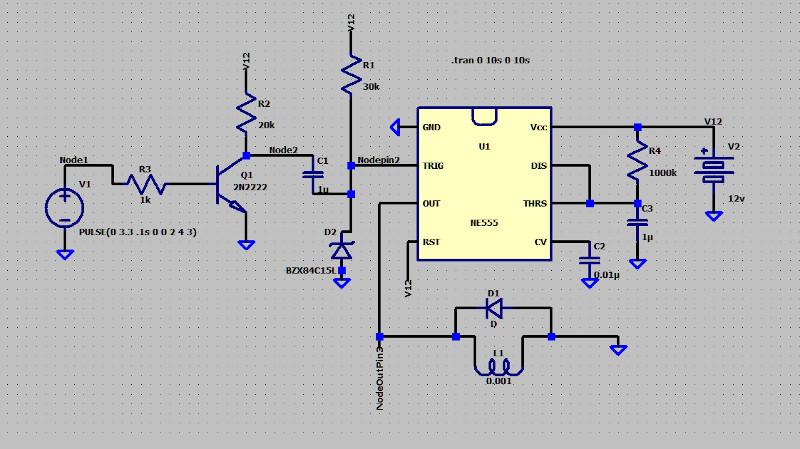
Traces from the simulator:
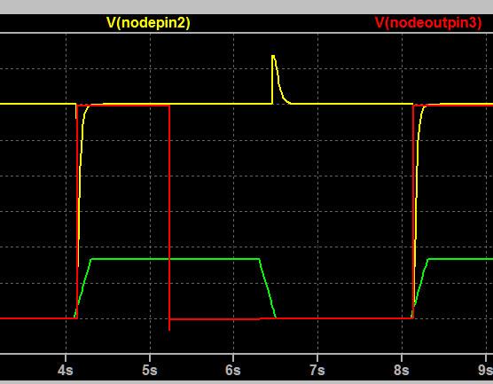
The green trace is the input from the sensor, the yellow trace is at pin 2, and the red trace is the output at pin 3. Note the positive going pulse when the input drops back to zero. That is why the Zener diode is required to limit it. Here it is a 15v Zener diode.
The output from prototype the circuit: Here I am using 9 volts as I only have 12 volt Zeners.
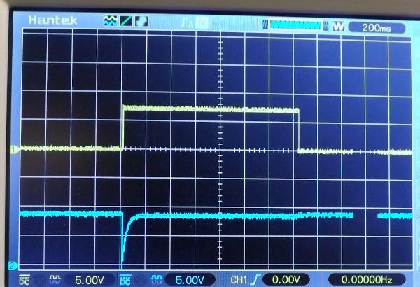
Here the blue trace is the trigger signal at pin 2 and the yellow trace is the output at pin 3 across a 150 ohm resistor for a relay load. The diode across the relay coil can be any general purpose diode like a 1N007 for example. The output is much wider then I would expect for R4 at 1Megohms and C3 at 1 microfarad. Expected 1 sec. not 1.4 There are numerous online calculators for calculating these values.
The values for the resistors are not critical except what you pick for R4:
- R1: 1000 to 1500 ohms
- R2; 20k to 30K "
- R3: 30K to 50K "
all work in the simulator.
https://www.electronics-lab.com/community/index.php?/topic/47824-555-timer-relay-driver-with-ttl-input/backrooms game
To pull pin 2 low, a transistor and capacitor setup seems to be the only viable option. 370 ohms is the resistance of my relay. thank you!
I am working with CS5484 for a project and I am unable to configure the IC
in Projects Q/A
Posted
Is github-link broken?