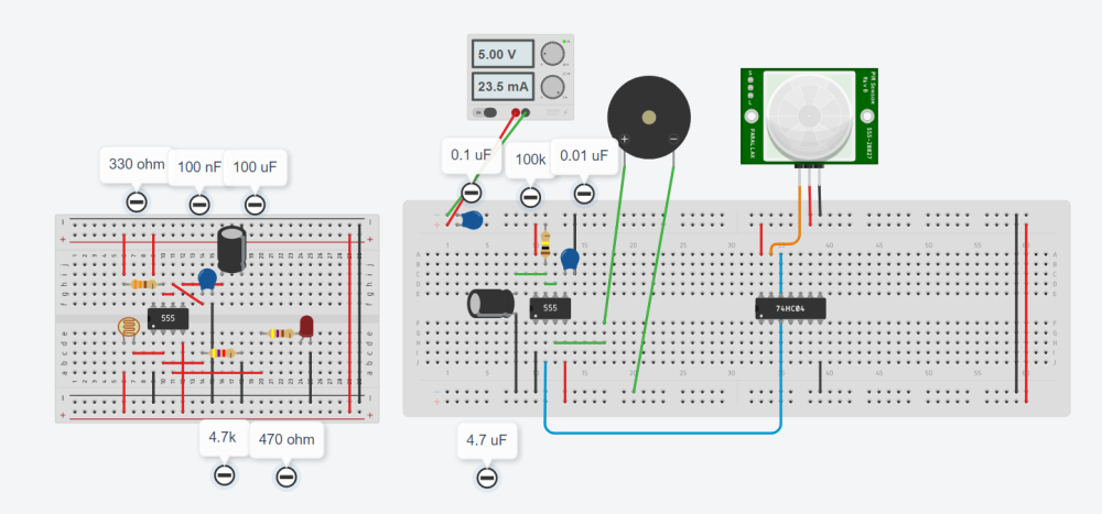
the circuit on the right is a darkness sensor while on the left is a motion detector using PIR. I want to combine these two circuits into one. The motion sensor must only function if the LDR detects darkness and it must not function if the LDR doesn't detect any darkness.
im making a school project, the circuit at the right is a darkness sensor using LDR and its steps and components are: STEP 1 - Connect 555 timer IC on the breadboard STEP 2 - Connect Pin 8 of 555 Timer to VCC of Battery and Pin 1 of 555 Timer to GND of Battery STEP 3 - Connect pin 4 to VCC and Connect pin 6 of 555 Timer to the pin 7 of 555 Timer STEP 4 - Connect 330-ohm resistor to pin 7 and pin 8 of IC STEP 5 - Connect 4.7uf polarized capacitor to pin 5 of IC and its negative side to the ground STEP 6 - Connect 0.01uf ceramic capacitor to pin 6 of IC and its negative side to the ground STEP 7 - Connect 4.7k ohm resistor on pin 2 of IC and its negative side to the ground STEP 8 - Connect LDR to pin 2 and VCC STEP 9 - Connect 470-ohm resistor to pin 3 of IC and connect its other side to the anode of the LED and its cathode to the ground STEP 10 - Test if the circuit works
while the circuit on the left is a motion detector alarm using PIR (HC-SR501) and its steps and components are: STEP 1 - Connect 555 timer IC on the breadboard and a 74HC04 IC STEP 2 - Connect Pin 8 of 555 Timer to VCC of Battery and Pin 1 of 555 Timer to GND of Battery. Also connect pin 14 of 74HC04 IC to VCC and pin 7 of 74HC04 IC to GND. STEP 3 - Connect pin 4 to VCC and Connect pin 6 of 555 Timer to the pin 7 of 555 Timer STEP 4 - Connect 100-kilo ohm resistor to pin 7 of 555 IC and its other side to the VCC STEP 5 - Connect 4.7uf polarized capacitor to pin 7 of 555 IC and its negative side to the ground STEP 6 - Connect 0.01uf ceramic capacitor to pin 5 of 555 IC and its negative side to the ground STEP 7 - Connect a buzzer to pin 3 of 555 IC and its negative side to the ground STEP 8 - Connect the pin 2 of 555 IC to pin 12 of 74HC04 IC STEP 9 - Connect the GND of PIR to the ground, its power pin to the VCC and its Signal/output to the pin 13 of 74HC04 IC STEP 10 - Test if the circuit works
do u have any suggestions on how we can merge the two circuit into one according to the said output?
I want to merge Darkness and PIR Motion Sensor into one circuit
in Electronic Projects Design/Ideas
Posted
the circuit on the right is a darkness sensor while on the left is a motion detector using PIR. I want to combine these two circuits into one. The motion sensor must only function if the LDR detects darkness and it must not function if the LDR doesn't detect any darkness.

im making a school project, the circuit at the right is a darkness sensor using LDR and its steps and components are:
STEP 1 - Connect 555 timer IC on the breadboard
STEP 2 - Connect Pin 8 of 555 Timer to VCC of Battery
and Pin 1 of 555 Timer to GND of Battery
STEP 3 - Connect pin 4 to VCC and Connect pin 6 of 555 Timer to the pin 7 of 555 Timer
STEP 4 - Connect 330-ohm resistor to pin 7 and pin 8 of IC
STEP 5 - Connect 4.7uf polarized capacitor to pin 5 of IC and its negative side to the ground
STEP 6 - Connect 0.01uf ceramic capacitor to pin 6 of IC and its negative side to the ground
STEP 7 - Connect 4.7k ohm resistor on pin 2 of IC and its negative side to the ground
STEP 8 - Connect LDR to pin 2 and VCC
STEP 9 - Connect 470-ohm resistor to pin 3 of IC and connect its other side to the anode of the LED and its cathode to the ground
STEP 10 - Test if the circuit works
while the circuit on the left is a motion detector alarm using PIR (HC-SR501) and its steps and components are:
STEP 1 - Connect 555 timer IC on the breadboard and a 74HC04 IC
STEP 2 - Connect Pin 8 of 555 Timer to VCC of Battery
and Pin 1 of 555 Timer to GND of Battery. Also connect pin 14 of 74HC04 IC to VCC and pin 7 of 74HC04 IC to GND.
STEP 3 - Connect pin 4 to VCC and Connect pin 6 of 555 Timer to the pin 7 of 555 Timer
STEP 4 - Connect 100-kilo ohm resistor to pin 7 of 555 IC and its other side to the VCC
STEP 5 - Connect 4.7uf polarized capacitor to pin 7 of 555 IC and its negative side to the ground
STEP 6 - Connect 0.01uf ceramic capacitor to pin 5 of 555 IC and its negative side to the ground
STEP 7 - Connect a buzzer to pin 3 of 555 IC and its negative side to the ground
STEP 8 - Connect the pin 2 of 555 IC to pin 12 of 74HC04 IC
STEP 9 - Connect the GND of PIR to the ground, its power pin to the VCC and its Signal/output to the pin 13 of 74HC04 IC
STEP 10 - Test if the circuit works
do u have any suggestions on how we can merge the two circuit into one according to the said output?