Search the Community
Showing results for tags 'ic 4017'.
Found 1 result
-
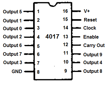
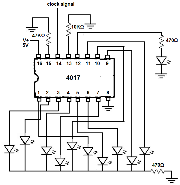
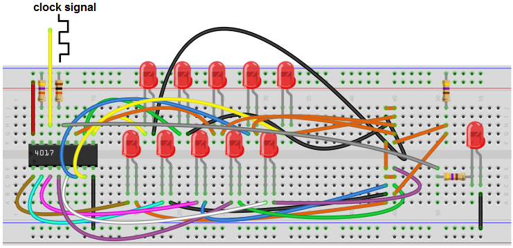
 A decade counter circuit operates by sequentially activating each of its output channels, one at a time, in a consecutive manner. For instance, if we construct a circuit featuring a decade counter along with 10 Light Emitting Diodes (LEDs), the decade counter will illuminate one LED at a time until all 10 LEDs are alight. This is the fundamental function of a decade counter. Essentially, it counts from one to ten, which aligns with its designation as a "decade" counter, signifying that it counts up to 10 (akin to a decade being comprised of 10 years). In this specific circuit, we will establish connections between 10 LEDs and our decade counter chip. The LEDs will activate individually, in sequence, until all of them are illuminated. Subsequently, the counter restarts the sequence, perpetually repeating this cycle. A decade counter is indeed an intriguing chip, owing to its versatility and the array of applications it accommodates. For this circuit, we will employ the widely used 4017 decade counter chip. A comprehensive description, encompassing its pin configuration, is provided below. Components Required: 4017 Decade Counter Chip 2 x 470 Ohm resistors 47 Kilohm resistor 10 Kilohm resistor 10 LEDs The 4017 is a readily available 16-pin integrated circuit, and it can be easily procured from various online distributors. A cost-effective source for this chip includes Jotrin Electronics, where you can also access a detailed guide via the following link: Jotrin Electronics - 4017 Decade Counter IC. The pinout for the 4017 is shown below. Out of the 16 pins on the 4017 chip, 10 are designated for output. These output pins are where we connect the components we want the chip to activate. In our case, we are using LEDs, with each LED attached to one of these output pins. The output pins are numbered from 0 to 9, and when the circuit is operational, they light up sequentially from 0 to 9. Two of the pins are used for power supply. V+ and GND are responsible for providing power to the 4017 chip. The chip operates at a 5V power supply. Therefore, we connect V+ to a 5V power source. The remaining pins include Reset, Clock, Enable, and Carry Out. Reset: This pin resets the count back to output 0. Normally, it is grounded, which means the reset function is inactive. When it is set to a HIGH voltage, it is triggered. So, if the circuit is in the process of counting up and reaches output 7, triggering the reset will take it back to output 0 once reset returns to a LOW state from a HIGH. Reset is active HIGH but is typically in a LOW state. Holding reset HIGH will keep the output at 0 and prevent the count from advancing. Clock: The clock is a crucial aspect of the 4017's operation. Without a clock signal, the 4017 chip remains idle. It progresses from one output to the next on the positive (rising) edge of a clock signal. As the clock transitions from LOW to HIGH, the 4017 chip commences and activates the next output. In essence, the chip's operation is synchronized with the clock signal. A faster clock signal results in quicker execution. If you're running the clock at 1Hz, the outputs will switch on with 1-second intervals. Increasing the clock speed to 5Hz means the intervals are now 200ms. At 5V, the maximum clock frequency is 2.5MHz, or 5.5MHz if you supply V+ with 15V. For this circuit, clock frequencies of about 1 to 10Hz are adequate for visual observation. Enable: The Enable pin is active low, which means it is typically connected to ground, rendering it active. When held LOW, the circuit counts up and operates. Setting this pin to HIGH halts all operation. Carry Out: The Carry Out pin goes HIGH once output 9 is reached and remains HIGH for outputs 0 to 4. It goes LOW for outputs 5 to 9. We can connect an LED to the Carry Out pin to observe this behavior. This covers all the pins' functionalities. The 4017 chip is quite straightforward and not challenging to understand or use. It's essential to note that only one output is active at any given time and turns off before the subsequent output activates. This sequence continues for all 10 outputs offered by the 4017 chip. So, when lighting up LEDs, all 10 LEDs illuminate one after the other until all have lit up. Then the decade counter resets, going from 0 to 9 again, repeating this process indefinitely. Its name, "decade counter," is due to its ability to count up to 10, from output 0 to output 9. 4017 Decade Counter Circuit The schematic diagram for the decade counter using the 4017 chip is shown below. Below is the breadboard layout for the circuit mentioned above. The initial step involves supplying power to the 4017 chip. Pin 16 of the chip receives a 5V input, while pin 8 is grounded. This action provides the necessary power for the chip to operate effectively. Subsequently, LEDs are connected to each of the outputs and the carryout pin. To prevent LED burnout, a 470Ω resistor is employed for the 10 LEDs connected to the outputs and the carryout pin. Both the reset and enable pins are kept at a LOW state during normal circuit operation. However, for testing purposes, these pins can be temporarily rewired from ground to the positive voltage rail to observe their impact. When the reset pin is briefly set to HIGH and then returned to a LOW state, the count resets to output 0 and then increments. Essentially, it restarts from the beginning. Setting the enable pin to HIGH will freeze the count. To enable this circuit to function correctly, a clock signal is essential. The most straightforward way to obtain this signal is by utilizing a function generator. With a function generator, you can effortlessly generate digital square wave signals and adjust the frequency as needed. In this scenario, we'd set it to 1Hz, which corresponds to one cycle per second. Consequently, there will be one low and one high signal per second. Consequently, you will witness a new LED lighting up every second. Afterward, you can fine-tune the frequency higher or lower. Increasing the frequency will accelerate the cycle. Consequently, the outputs will advance more rapidly, causing the LEDs to illuminate more quickly. Conversely, if you reduce the frequency to, say, 0.5Hz, the period (T) becomes T= 1/f= 1/0.5Hz= 2 seconds. As a result, there will be a 2-second interval between each LED activation. In the absence of a function generator, an alternative option is to construct a voltage-controlled oscillator to generate the clock signal. This can be achieved using a 4046 phase-locked loop chip, which, when correctly configured, produces digital square waves at pin 4. As a result, pin 4 of the VCO circuit should be connected to pin 14 of the 4017 chip. Upon activation, each LED should illuminate sequentially, commencing from output 0 and progressing up to output 9. This sequence repeats infinitely.