Search the Community
Showing results for tags 'ldr circuit'.
-
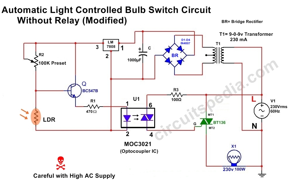
When Light fall on LDR in DAY then the Resistance of LDR goes LOW And at this situation the maximum voltage Dropped With Negative supply (Ground) by cross through LDR and Voltage at the Base of transistor Q1 is Very LOW. When the Voltage goes to very LOW (Below0.7v) at BASE of Q1 then Transistor not get ON and no Power flows between COLLECTOR and EMITTER. Gate Voltagr of TRIAC is LOW. Now TRIAC Remain OFF Because It not TRIGGERED. At Night Time when no light incident on LDR then the internal Resistance of LDR comes HIGH and Very less amount of Power cross through LDR to ground , then the Voltage At base Terminal of transistor become increase (above 0.7v) and now transistor turn ON and current starts flow between Emitter and COLLECTOR. Therefor the Voltage increasing at GATE of TRIAC BT136. As voltage increase at GATE then TRIAC get Triggered . After Triac triggerd it Turn on and Passes the Power Supply between terminal 2 to terminal 1 and Bulb Switched On. For more sensitivity use 2 LDR with parallel. For more detail go to http://www.circuitspedia.com/automatic-light-controlled-bulb-switch-using-without-relay/ And also go to http://www.circuitspedia.com/category/light-operated-switch-circuit/
-
- automatic on off switch
- light operated switch circuit
- (and 7 more)

.thumb.png.2654eb08e8864dfcee99bc0732f95fd2.png)
