Search the Community
Showing results for tags 'seeed studio'.
Found 5 results
-
The Xiao esp32 s3 sense is a tiny but powerful development board that integrates the ESP32-S3R8 processor, which supports 2.4GHz Wi-Fi and Bluetooth 5.0 wireless connectivity, 8MB PSRAM, 8MB flash memory, and a rich set of interfaces. The Xiao esp32 s3 sense also comes with a detachable OV2640 camera sensor, a digital microphone, and an SD card slot, which enable various applications in the fields of intelligent voice and vision AI. The xiao esp32 s3 sense is compatible with the Arduino IDE and MicroPython, which makes it easy to program and use. It also supports low-power consumption modes, battery charging, and multiple themes and information display. The Xiao esp32 s3 sense is suitable for space-limited projects, such as wearable devices, IoT devices, and embedded ML devices. In this article, I will show you how to get started with the Xiao esp32 s3 sense, how to use the camera and SD card features, and how to customize and optimize the board. Let’s begin! Get PCBs for Your Projects Manufactured This project was successfully completed because of the help and support from NextPCB. Guys if you have a PCB project, please visit their website and get exciting discounts and coupons. NextPCB offers high-quality, reliable PCB starting at $1.9, and multilayer starting at $6.9. Also, everyone can enjoy free PCB assembly for 5 boards! Also, NextPCB is having a year end sale in which anyone can register through their website and get a $30 Coupon which can be used for ordering PCBs. You can also try HQDFM free online PCB Gerber viewer to check your PCB design and avoid costly errors. Capturing and Displaying Images The Xiao esp32 s3 sense comes with a detachable OV2640 camera sensor, which can capture images up to 2 megapixels. The camera sensor is connected to the board via a 24-pin FPC cable, which can be easily plugged in or unplugged. The camera sensor can be mounted on the board using the provided screws, or placed anywhere you want using the extension cable. To capture and display images, you need to use the CameraWebServer example sketch from the Arduino IDE. This sketch will create a web server on the Xiao esp32 s3 sense, which will allow you to access the camera stream from any web browser on your local network. You can also take snapshots and save them to the SD card or the flash memory. To use the CameraWebServer sketch, you need to follow these steps: Open the Arduino IDE and select the Xiao esp32 s3 sense board from the Tools menu. Go to File > Examples > ESP32 > Camera > CameraWebServer and open the sketch. In the sketch, find the line that says #define CAMERA_MODEL_AI_THINKER and uncomment it. This will select the correct camera model for the Xiao ESP32 s3 sense. #include "esp_camera.h" #include <WiFi.h> #define CAMERA_MODEL_XIAO_ESP32S3 // Has PSRAM #include "camera_pins.h" // =========================== // Enter your WiFi credentials // =========================== const char* ssid = "ELDRADO"; const char* password = "amazon123"; void startCameraServer(); void setupLedFlash(int pin); void setup() { Serial.begin(115200); while(!Serial); Serial.setDebugOutput(true); Serial.println(); camera_config_t config; config.ledc_channel = LEDC_CHANNEL_0; config.ledc_timer = LEDC_TIMER_0; config.pin_d0 = Y2_GPIO_NUM; config.pin_d1 = Y3_GPIO_NUM; config.pin_d2 = Y4_GPIO_NUM; config.pin_d3 = Y5_GPIO_NUM; config.pin_d4 = Y6_GPIO_NUM; config.pin_d5 = Y7_GPIO_NUM; config.pin_d6 = Y8_GPIO_NUM; config.pin_d7 = Y9_GPIO_NUM; config.pin_xclk = XCLK_GPIO_NUM; config.pin_pclk = PCLK_GPIO_NUM; config.pin_vsync = VSYNC_GPIO_NUM; config.pin_href = HREF_GPIO_NUM; config.pin_sscb_sda = SIOD_GPIO_NUM; config.pin_sscb_scl = SIOC_GPIO_NUM; config.pin_pwdn = PWDN_GPIO_NUM; config.pin_reset = RESET_GPIO_NUM; config.xclk_freq_hz = 20000000; config.frame_size = FRAMESIZE_UXGA; config.pixel_format = PIXFORMAT_JPEG; // for streaming //config.pixel_format = PIXFORMAT_RGB565; // for face detection/recognition config.grab_mode = CAMERA_GRAB_WHEN_EMPTY; config.fb_location = CAMERA_FB_IN_PSRAM; config.jpeg_quality = 12; config.fb_count = 1; // if PSRAM IC present, init with UXGA resolution and higher JPEG quality // for larger pre-allocated frame buffer. if(config.pixel_format == PIXFORMAT_JPEG){ if(psramFound()){ config.jpeg_quality = 10; config.fb_count = 2; config.grab_mode = CAMERA_GRAB_LATEST; } else { // Limit the frame size when PSRAM is not available config.frame_size = FRAMESIZE_SVGA; config.fb_location = CAMERA_FB_IN_DRAM; } } else { // Best option for face detection/recognition config.frame_size = FRAMESIZE_240X240; #if CONFIG_IDF_TARGET_ESP32S3 config.fb_count = 2; #endif } // camera init esp_err_t err = esp_camera_init(&config); if (err != ESP_OK) { Serial.printf("Camera init failed with error 0x%x", err); return; } sensor_t * s = esp_camera_sensor_get(); // initial sensors are flipped vertically and colors are a bit saturated if (s->id.PID == OV3660_PID) { s->set_vflip(s, 1); // flip it back s->set_brightness(s, 1); // up the brightness just a bit s->set_saturation(s, -2); // lower the saturation } // drop down frame size for higher initial frame rate if(config.pixel_format == PIXFORMAT_JPEG){ s->set_framesize(s, FRAMESIZE_QVGA); } // Setup LED FLash if LED pin is defined in camera_pins.h #if defined(LED_GPIO_NUM) setupLedFlash(LED_GPIO_NUM); #endif WiFi.begin(ssid, password); WiFi.setSleep(false); while (WiFi.status() != WL_CONNECTED) { delay(500); Serial.print("."); } Serial.println(""); Serial.println("WiFi connected"); startCameraServer(); Serial.print("Camera Ready! Use 'http://"); Serial.print(WiFi.localIP()); Serial.println("' to connect"); } void loop() { // Do nothing. Everything is done in another task by the web server delay(10000); } In the sketch, find the line that says const char* ssid = "your-ssid"; and replace your-ssid with the name of your Wi-Fi network. Do the same for the line that says const char* password = "your-password"; and replace your-password with the password of your Wi-Fi network. Upload the sketch to the Xiao esp32 s3 sense and open the serial monitor. You should see the IP address of the web server, such as http://192.168.1.100. Open any web browser on your computer or smartphone and enter the IP address of the web server. You should see the camera stream and some buttons and options on the web page. Adjusting the Resolution and Orientation The xiao esp32 s3 sense can capture images at different resolutions, ranging from 160x120 to 1600x1200. You can change the resolution from the web page by selecting one of the options from the drop-down menu. The higher the resolution, the better the image quality, but the slower the frame rate and the more memory usage. You can also change the orientation of the camera from the web page by clicking on the buttons that say “Flip” or “Rotate”. The flip button will flip the image horizontally, while the rotate button will rotate the image 90 degrees clockwise. Using the Webcam Web Application The Xiao esp32 s3 sense can also be used as a webcam for your computer. It allows you to use the camera sensor as a video input device for any software that supports webcams, such as Skype, Zoom, OBS, etc. To use the webcam web application, you need to follow these steps: Install and run the VLC on your computer. You should see a window with a preview of the camera stream and some settings. In the settings, enter the IP address of the web server, such as http://192.168.1.100:81/stream. Click on the “Start” button to start the webcam service. Open any software that supports webcams and select the Xiao esp32 s3 sense as the video input device. You should see the camera stream on the software. Storing and Accessing Data The Xiao esp32 s3 sense comes with an SD card slot that can support microSD cards up to 32GB. The SD card slot can be used to store and access data, such as images, videos, audio, text, etc. You can also use the SD card as secondary storage for your programs, libraries, or data files. Before using the SD card on the Xiao ESP32 s3 sense, you need to format the SD card to FAT32 format. This is the most compatible and widely used format for SD cards. You can use any tool or software that can format SD cards to FAT32 format, such as the SD Card Formatter, the Disk Management tool on Windows, the Disk Utility tool on Mac, etc. After formatting the SD card, you need to insert the SD card into the SD card slot on the Xiao ESP32 s3 sense. Please note the direction of insertion, the side with the gold finger should face inward. The SD card slot has a spring mechanism that will lock the SD card in place. To eject the SD card, you need to press the SD card gently and release it. To store and access data on the SD card, you need to use the SD library from the Arduino IDE. This library provides functions to create, read, write, delete, and list files and directories on the SD card. You can also use the File object to manipulate the files and directories on the SD card. #include "FS.h" #include "SD.h" #include "SPI.h" void listDir(fs::FS &fs, const char * dirname, uint8_t levels){ Serial.printf("Listing directory: %s\n", dirname); File root = fs.open(dirname); if(!root){ Serial.println("Failed to open directory"); return; } if(!root.isDirectory()){ Serial.println("Not a directory"); return; } File file = root.openNextFile(); while(file){ if(file.isDirectory()){ Serial.print(" DIR : "); Serial.println(file.name()); if(levels){ listDir(fs, file.path(), levels -1); } } else { Serial.print(" FILE: "); Serial.print(file.name()); Serial.print(" SIZE: "); Serial.println(file.size()); } file = root.openNextFile(); } } void createDir(fs::FS &fs, const char * path){ Serial.printf("Creating Dir: %s\n", path); if(fs.mkdir(path)){ Serial.println("Dir created"); } else { Serial.println("mkdir failed"); } } void removeDir(fs::FS &fs, const char * path){ Serial.printf("Removing Dir: %s\n", path); if(fs.rmdir(path)){ Serial.println("Dir removed"); } else { Serial.println("rmdir failed"); } } void readFile(fs::FS &fs, const char * path){ Serial.printf("Reading file: %s\n", path); File file = fs.open(path); if(!file){ Serial.println("Failed to open file for reading"); return; } Serial.print("Read from file: "); while(file.available()){ Serial.write(file.read()); } file.close(); } void writeFile(fs::FS &fs, const char * path, const char * message){ Serial.printf("Writing file: %s\n", path); File file = fs.open(path, FILE_WRITE); if(!file){ Serial.println("Failed to open file for writing"); return; } if(file.print(message)){ Serial.println("File written"); } else { Serial.println("Write failed"); } file.close(); } void appendFile(fs::FS &fs, const char * path, const char * message){ Serial.printf("Appending to file: %s\n", path); File file = fs.open(path, FILE_APPEND); if(!file){ Serial.println("Failed to open file for appending"); return; } if(file.print(message)){ Serial.println("Message appended"); } else { Serial.println("Append failed"); } file.close(); } void renameFile(fs::FS &fs, const char * path1, const char * path2){ Serial.printf("Renaming file %s to %s\n", path1, path2); if (fs.rename(path1, path2)) { Serial.println("File renamed"); } else { Serial.println("Rename failed"); } } void deleteFile(fs::FS &fs, const char * path){ Serial.printf("Deleting file: %s\n", path); if(fs.remove(path)){ Serial.println("File deleted"); } else { Serial.println("Delete failed"); } } void testFileIO(fs::FS &fs, const char * path){ File file = fs.open(path); static uint8_t buf[512]; size_t len = 0; uint32_t start = millis(); uint32_t end = start; if(file){ len = file.size(); size_t flen = len; start = millis(); while(len){ size_t toRead = len; if(toRead > 512){ toRead = 512; } file.read(buf, toRead); len -= toRead; } end = millis() - start; Serial.printf("%u bytes read for %u ms\n", flen, end); file.close(); } else { Serial.println("Failed to open file for reading"); } file = fs.open(path, FILE_WRITE); if(!file){ Serial.println("Failed to open file for writing"); return; } size_t i; start = millis(); for(i=0; i<2048; i++){ file.write(buf, 512); } end = millis() - start; Serial.printf("%u bytes written for %u ms\n", 2048 * 512, end); file.close(); } void setup(){ Serial.begin(115200); while(!Serial); if(!SD.begin(21)){ Serial.println("Card Mount Failed"); return; } uint8_t cardType = SD.cardType(); if(cardType == CARD_NONE){ Serial.println("No SD card attached"); return; } Serial.print("SD Card Type: "); if(cardType == CARD_MMC){ Serial.println("MMC"); } else if(cardType == CARD_SD){ Serial.println("SDSC"); } else if(cardType == CARD_SDHC){ Serial.println("SDHC"); } else { Serial.println("UNKNOWN"); } uint64_t cardSize = SD.cardSize() / (1024 * 1024); Serial.printf("SD Card Size: %lluMB\n", cardSize); listDir(SD, "/", 0); createDir(SD, "/mydir"); listDir(SD, "/", 0); removeDir(SD, "/mydir"); listDir(SD, "/", 2); writeFile(SD, "/hello.txt", "Hello "); appendFile(SD, "/hello.txt", "World!\n"); readFile(SD, "/hello.txt"); deleteFile(SD, "/foo.txt"); renameFile(SD, "/hello.txt", "/foo.txt"); readFile(SD, "/foo.txt"); testFileIO(SD, "/test.txt"); Serial.printf("Total space: %lluMB\n", SD.totalBytes() / (1024 * 1024)); Serial.printf("Used space: %lluMB\n", SD.usedBytes() / (1024 * 1024)); } void loop(){ } Here is the serial terminal response. Wrap-Up: In this article, I have shown how to use the Xiao Esp32 S3 Sense Camera and SD card future. Hope you guys found this helpful. Will see you another one. Bye.
-
 This guide explains the steps to seamlessly integrate the WM1110 sensor module with The Things Network (TTN) and ThingSpeak for data transmission and visualization. The seeed studio Wio-WM1110 Dev Kit is based on the Wio-WM1110 Wireless Module, which integrates both a Semtech LoRa® transceiver and a multi-purpose radio front-end for geolocation functionalities. The LoRa® transceiver enables low-power, high-sensitivity network coverage, while GNSS (GPS/BeiDou) and Wi-Fi scanning work together to offer comprehensive location coverage. Additionally, the Dev Kit provides connectivity options for a variety of peripherals, making it a versatile platform for developing diverse IoT applications. The Wio-WM1110 is a powerful fusion positioning module designed for developing low-power, long-range IoT applications. It combines the capabilities of the Semtech LR1110 LoRa transceiver and the Nordic nRF52840 microcontroller, offering a comprehensive solution for building connected devices with the following features: Long-range wireless communication: Utilizing Semtech's LoRa technology, the Wio-WM1110 enables low-power communication over vast distances, making it ideal for connecting devices in remote locations. Global Navigation Satellite System (GNSS): Integrated GNSS support, including GPS and BeiDou, provides accurate location tracking capabilities for your IoT devices. Wi-Fi connectivity: In addition to LoRaWAN and GNSS, the Wio-WM1110 also offers Wi-Fi connectivity, providing another option for device communication and internet access. Bluetooth: The module further extends its connectivity options by supporting Bluetooth protocols, enabling communication with other Bluetooth-enabled devices. Fusion positioning: By combining the data from LoRaWAN, GNSS, Wi-Fi, and Bluetooth, the Wio-WM1110 can achieve highly accurate and reliable positioning, even in challenging environments. Low-power operation: The Wio-WM1110 is designed for low-power consumption, allowing your devices to operate for extended periods on battery power. Open-source platform: The Wio-WM1110 is based on an open-source platform, providing developers with access to the underlying hardware and software, allowing for greater customization and flexibility. Get PCBs for Your Projects Manufactured This project was successfully completed because of the help and support from NextPCB. Guys if you have a PCB project, please visit their website and get exciting discounts and coupons. NextPCB offers high-quality, reliable PCB starting at $1.9, and multilayer starting at $6.9. Also, everyone can enjoy free PCB assembly for 5 boards! Also, NextPCB is having a year end sale in which anyone can register through their website and get a $30 Coupon which can be used for ordering PCBs. You can also try HQDFM free online PCB Gerber viewer to check your PCB design and avoid costly errors. Let's learn what WM1110 is. The Seeed Studio Wio-WM1110 is not just a blend of the Semtech LR1110 and Nordic nRF52840, it's a powerful fusion of these two technologies, creating a development platform with exceptional capabilities for building low-power, long-range IoT applications. LR1110 Features LR1110 Block diagram Low-Power, High-Sensitivity LoRa®/(G)FSK Half-Duplex RF Transceiver Supports worldwide ISM frequency bands in the range of 150 MHz to 960 MHz. Features a low-noise figure RX front-end for enhanced LoRa®/(G)FSK sensitivity. Offers two high-power PA paths: +22 dBm and +15 dBm, with a high-efficiency PA path at +15 dBm. Provides a long-range FHSS (LR-FHSS) modulator. Includes an integrated PA regulator supply selector for simplified dual power (+15 dBm/+22 dBm) implementation with one board design. Supports worldwide multi-region BoMs, with the circuit adapting to matching networks to satisfy regulatory limits. Fully compatible with SX1261/2/8 devices and the LoRaWAN® standard, defined by the LoRa Alliance®. Multi-Purpose Radio Front-End for Geolocation Applications GNSS (GPS/BeiDou) low-power scanning 802.11b/g/n Wi-Fi ultra-low-power passive scanning 150 - 2700 MHz continuous frequency coverage High-bandwidth RX ADC (up to 24 MHz DSB) Digital baseband processing Cryptographic Engine: Securing Your LoRaWAN Applications The Wio-WM1110 integrates a powerful cryptographic engine to safeguard your LoRaWAN applications. Here's a breakdown of its key features: Hardware-Accelerated Encryption/Decryption: Provides efficient AES-128 encryption and decryption, crucial for securing data communication in LoRaWAN networks. Dedicated hardware offloads the processing burden from the main CPU, enhancing performance and reducing power consumption. Device Parameter Management: Securely stores and manages device parameters like DevEUI and JoinEUI, defined by the LoRa Alliance. These unique identifiers are essential for device authentication and network access, and the cryptographic engine ensures their integrity and confidentiality. Enhanced Security: Protects sensitive information like encryption keys from unauthorized access, preventing potential breaches and data leaks. Offers a secure environment for storing critical data like NwkKey and AppKey, as defined in the LoRaWAN standard. Overall, the cryptographic engine plays a crucial role in safeguarding the security and reliability of your LoRaWAN applications. It provides comprehensive protection for sensitive data and facilitates secure communication within the network. NRF52840 Features The NRF52840 is a powerful and versatile Bluetooth Low Energy (BLE) SoC from Nordic Semiconductor, offering a wide range of features for various IoT applications. Here's a breakdown of its key highlights: NRF52840 Block Diagram CPU and Memory: 64 MHz Arm Cortex-M4F CPU with FPU: Delivers ample processing power for running complex applications. 1 MB Flash memory: Stores application code and data. 256 KB RAM: Provides sufficient memory for application execution and data handling. Wireless Connectivity: Bluetooth 5.3: Supports the latest Bluetooth standard for long-range, high throughput, and improved security. 2 Mbps PHY: Enables faster data transfer compared to previous Bluetooth versions. Long Range: Achieves extended communication range for IoT applications. 802.15.4: Supports additional protocols like Thread and Zigbee for wider ecosystem compatibility. Peripherals and Interfaces: Multiple GPIOs: Enables connection to various sensors, actuators, and peripherals. High-speed SPI and QSPI: Offers fast data transfer for external memory and displays. PDM and I2S: Supports digital microphones and audio applications. Full-speed USB device: Enables data transfer and battery charging. ADC and DAC: Allows analog signal acquisition and generation. Power Management: Ultra-low power consumption: Enables long battery life for IoT devices. Multiple power saving modes: Dynamically adjusts power consumption based on application requirements. Security: Hardware Cryptographic Engine: Provides secure data encryption and decryption. Secure Boot: Ensures only authorized code can be executed on the device. Other Features: Real-time clock (RTC): Enables accurate timekeeping. Temperature sensor: Provides temperature readings for environmental monitoring. On-chip debugger: Simplifies development and debugging process. Open-source platform: Access to extensive resources and libraries for easier development and customization. Overall, the NRF52840 is a powerful and feature-rich SoC that empowers developers to build innovative and efficient IoT solutions with low power consumption and robust capabilities. Wio-WM1110 Dev Kit Block Diagram & Hardware Overview Wio-WM1110 Dev Kit Block Diagram Hardware Overview Pinout Pin Diagram Specifications 1 / 3 Firmware Development for Wio-WM1110 Before we begin developing, we will need the following tools to complete this Getting Started Guide. Preparation Wio-WM1110 Dev Kit x 1 Computer x 1 USB Type-C Cable x 1 USB Type-B Cable x 1 J-Link Debug Programmer(or nRF52dk) x 1 Power on the Wio-WM1110 Dev Board and connect the J-Link Debug Programmer to the board as follows: Connect the nRF52 DK's J-Link SWD pins (SWDIO and SWCLK) to the Wio-WM1110 Dev Board's SWD pins (SWDIO and SWCLK) to flash the firmware CONNECTION: 3V3 (Wio-WM1110 Dev Board) -> VTG (J-Link Debug Programmer nrf52dk)CLK (Wio-WM1110 Dev Board) -> SWCLK (J-Link Debug Programmer nrf52dk)DIO (Wio-WM1110 Dev Board) -> SWDIO (J-Link Debug Programmer nrf52dk)GND (Wio-WM1110 Dev Board) -> GND (J-Link Debug Programmer nrf52dk) Programming Software: A variety of programming software options exist for developing firmware on the WM1110. I have tested the module using Arduino IDE, PlatformIO, Keil uVision, Visual Studio Code, SEGGER Embedded Studio (SES), and Mbed Studio. From my experience, Mbed Studio and SEGGER Embedded Studio (SES) offer the most user-friendly experience for firmware development. This Getting Started guide will utilize SEGGER Embedded Studio (SES) for developing the firmware. SEGGER Embedded Studio (SES) is a comprehensive and user-friendly IDE for managing, building, testing, and deploying embedded applications. This translates to smooth and efficient development operations thanks to its extensive feature set. Powerful Project Management: Effortlessly manage your Wio-WM1110 firmware projects, regardless of size or complexity, with SES's robust project management tools. Seamless Version Control: Leverage built-in version control features to track changes and deploy applications automatically. Integrated Build and Debugging Tools: Utilize SES's powerful integrated build and debugging tools to streamline your Wio-WM1110 firmware development workflow. Installing SEGGER Embedded Studio : The software can be downloaded from this link: It's recommended to use the 5.68 version.https://www.segger.com/downloads/embedded-studio/ Download the nRF5 SDK and place it in the same directory where SEGGER Embedded Studio is installed. The nRF5 SDK provides a comprehensive development environment for nRF5 Series devices. It includes a broad selection of drivers, libraries, examples for peripherals, SoftDevices, and proprietary radio protocols. All code examples within the SDK are specifically designed to compile and run on the Wio-WM1110 Dev Kit, streamlining your development process. The software can be downloaded from this link: nRF5 SDK-Download Download the Seeed Example Package and place it in the same directory where the nRF5 SDK is installed. The Seeed Example Package can be downloaded from this link:Seeed Example-Download Seeed Studio provides an example project to jumpstart developers' progress. This project encompasses LoRaWAN communication, positioning information acquisition, onboard sensor data acquisition, and more. Add Seeed Example file to nRF5 SDK Copy the Seeed Example file to the following path of nRF5 SDK: .../nRF5_SDK_17.1.0_ddde560/examples/peripheral/ Testing the Wio-WM1110's Onboard LED with a Blinky Example The Blinky Example code is readily available within the "Example" folder. Access the code by navigating to the "Open solution" tab. Compiling the test application Select "Build" > "Compile project_target". Programming the test application After compiling the application, you can program it to the Dev board. Click "Target" -- "Connect J-Link" Click "Build" -- "Build and Run" to build the blinky project. You will see "Download successful" when it has been completed. Then the 2 LEDs on the board will blink as follows. Example code for Seamless Integration of WM1110 using TTN and ThingSpeak. In this project, the onboard temperature and humidity sensors of the WM1110 development kit are used to collect data. This sensor data is sent to ThingSpeak for data transmission and visualization, utilizing TTN webhooks integration. Before diving straight into LoRaWAN integration, we need to learn the LR1110's instructions to integrate it with the code. Otherwise, it won't be easy to understand the code. First, learn about LoRaWAN from the Semtech Learning Center. Here is the link to the courses: https://learn.semtech.com/ Next, go through the LoRa Basics™ Modem User Manual for comprehensive instructions on handling the LoRaWAN protocol. Setup the LoRaWAN Configuration keys Wio-WM1110 DK allows users to set the DevEUI, AppEUI, and AppKey, so you can set up our parameters in the 'lorawan_key_config.h' file Based on the operating region, you must specify the LORAWAN_REGION. The AppEUI key is user-defined and requires manual entry during registration. In the current example project, I have manually entered the AppEUI key. Device Registering on LoRaWAN® Network Server(TTN) To begin, register for an account with The Things Industries or The Things Network. Step 1: Create an application Navigate to the Applications page, and click "+Create application". Enter an application ID in lowercase letters and numbers only. You may also use the hyphen (-) symbol. Click Create Application to save your changes. Step 2: Register the Device Click "Register end device". Set the following parameters: Frequency Plan: Select the appropriate Frequency plan for the target region LoRaWAN version:LoRaWAN Specification 1.0.3 The remaining keys, DevEUI and AppKey, can be generated using automated tools. Here are the actual settings that I specifically configured for the current example project. For a better understanding of how to integrate the whole process, please follow the video provided below. Code #include "main_lorawan.h" #include "lorawan_key_config.h" #include "smtc_board.h" #include "smtc_hal.h" #include "apps_modem_common.h" #include "apps_modem_event.h" #include "smtc_modem_api.h" #include "device_management_defs.h" #include "smtc_board_ralf.h" #include "apps_utilities.h" #include "smtc_modem_utilities.h" float temp = 0, humi = 0; #define xstr( a ) str( a ) #define str( a ) #a static uint8_t stack_id = 0; static uint8_t app_data_buffer[LORAWAN_APP_DATA_MAX_SIZE]; static void send_frame( const uint8_t* buffer, const uint8_t length, const bool confirmed ); static void parse_downlink_frame( uint8_t port, const uint8_t* payload, uint8_t size ); static void on_modem_reset( uint16_t reset_count ); static void on_modem_network_joined( void ); static void on_modem_alarm( void ); static void on_modem_tx_done( smtc_modem_event_txdone_status_t status ); static void on_modem_down_data( int8_t rssi, int8_t snr, smtc_modem_event_downdata_window_t rx_window, uint8_t port, const uint8_t* payload, uint8_t size ); int main( void ) { hal_debug_init( ); hal_i2c_master_init( ); hal_gpio_init_out( SENSOR_POWER, HAL_GPIO_SET ); hal_mcu_wait_ms( 10 ); // wait power on SHT41Init( ); static apps_modem_event_callback_t smtc_event_callback = { .adr_mobile_to_static = NULL, .alarm = on_modem_alarm, .almanac_update = NULL, .down_data = on_modem_down_data, .join_fail = NULL, .joined = on_modem_network_joined, .link_status = NULL, .mute = NULL, .new_link_adr = NULL, .reset = on_modem_reset, .set_conf = NULL, .stream_done = NULL, .time_updated_alc_sync = NULL, .tx_done = on_modem_tx_done, .upload_done = NULL, }; /* Initialise the ralf_t object corresponding to the board */ ralf_t* modem_radio = smtc_board_initialise_and_get_ralf( ); /* Disable IRQ to avoid unwanted behaviour during init */ hal_mcu_disable_irq( ); /* Init board and peripherals */ hal_mcu_init( ); smtc_board_init_periph( ); /* Init the Lora Basics Modem event callbacks */ apps_modem_event_init( &smtc_event_callback ); /* Init the modem and use apps_modem_event_process as event callback, please note that the callback will be called * immediately after the first call to modem_run_engine because of the reset detection */ smtc_modem_init( modem_radio, &apps_modem_event_process ); /* Re-enable IRQ */ hal_mcu_enable_irq( ); HAL_DBG_TRACE_MSG( "\n" ); HAL_DBG_TRACE_INFO( "###### ===== LoRa Basics Modem LoRaWAN Class A/C demo application ==== ######\n\n" ); /* LoRa Basics Modem Version */ apps_modem_common_display_lbm_version( ); /* Configure the partial low power mode */ hal_mcu_partial_sleep_enable( APP_PARTIAL_SLEEP ); while( 1 ) { /* Execute modem runtime, this function must be called again in sleep_time_ms milliseconds or sooner. */ uint32_t sleep_time_ms = smtc_modem_run_engine( ); SHT41GetTempAndHumi( &temp, &humi ); //HAL_DBG_TRACE_INFO( "temp = %.1f, humi = %.1f\r\n", temp, humi ); hal_mcu_set_sleep_for_ms( sleep_time_ms ); } } static void on_modem_reset( uint16_t reset_count ) { HAL_DBG_TRACE_INFO( "Application parameters:\n" ); HAL_DBG_TRACE_INFO( " - LoRaWAN uplink Fport = %d\n", LORAWAN_APP_PORT ); HAL_DBG_TRACE_INFO( " - DM report interval = %d\n", APP_TX_DUTYCYCLE ); HAL_DBG_TRACE_INFO( " - Confirmed uplink = %s\n", ( LORAWAN_CONFIRMED_MSG_ON == true ) ? "Yes" : "No" ); apps_modem_common_configure_lorawan_params( stack_id ); ASSERT_SMTC_MODEM_RC( smtc_modem_join_network( stack_id ) ); } static void on_modem_network_joined( void ) { ASSERT_SMTC_MODEM_RC( smtc_modem_alarm_start_timer( APP_TX_DUTYCYCLE ) ); ASSERT_SMTC_MODEM_RC( smtc_modem_adr_set_profile( stack_id, LORAWAN_DEFAULT_DATARATE, adr_custom_list ) ); } static void on_modem_alarm( void ) { smtc_modem_status_mask_t modem_status; uint32_t charge = 0; uint8_t app_data_size = 0; /* Schedule next packet transmission */ ASSERT_SMTC_MODEM_RC( smtc_modem_alarm_start_timer( APP_TX_DUTYCYCLE ) ); HAL_DBG_TRACE_PRINTF( "smtc_modem_alarm_start_timer: %d s\n\n", APP_TX_DUTYCYCLE ); ASSERT_SMTC_MODEM_RC( smtc_modem_get_status( stack_id, &modem_status ) ); modem_status_to_string( modem_status ); app_data_buffer[app_data_size++] = temp; app_data_buffer[app_data_size++] = humi; send_frame( app_data_buffer, app_data_size, LORAWAN_CONFIRMED_MSG_ON ); } static void on_modem_tx_done( smtc_modem_event_txdone_status_t status ) { static uint32_t uplink_count = 0; HAL_DBG_TRACE_INFO( "Uplink count: %d\n", ++uplink_count ); } static void on_modem_down_data( int8_t rssi, int8_t snr, smtc_modem_event_downdata_window_t rx_window, uint8_t port, const uint8_t* payload, uint8_t size ) { HAL_DBG_TRACE_INFO( "Downlink received:\n" ); HAL_DBG_TRACE_INFO( " - LoRaWAN Fport = %d\n", port ); HAL_DBG_TRACE_INFO( " - Payload size = %d\n", size ); HAL_DBG_TRACE_INFO( " - RSSI = %d dBm\n", rssi - 64 ); HAL_DBG_TRACE_INFO( " - SNR = %d dB\n", snr >> 2 ); switch( rx_window ) { case SMTC_MODEM_EVENT_DOWNDATA_WINDOW_RX1: { HAL_DBG_TRACE_INFO( " - Rx window = %s\n", xstr( SMTC_MODEM_EVENT_DOWNDATA_WINDOW_RX1 ) ); break; } case SMTC_MODEM_EVENT_DOWNDATA_WINDOW_RX2: { HAL_DBG_TRACE_INFO( " - Rx window = %s\n", xstr( SMTC_MODEM_EVENT_DOWNDATA_WINDOW_RX2 ) ); break; } case SMTC_MODEM_EVENT_DOWNDATA_WINDOW_RXC: { HAL_DBG_TRACE_INFO( " - Rx window = %s\n", xstr( SMTC_MODEM_EVENT_DOWNDATA_WINDOW_RXC ) ); break; } } if( size != 0 ) { HAL_DBG_TRACE_ARRAY( "Payload", payload, size ); } } static void send_frame( const uint8_t* buffer, const uint8_t length, bool tx_confirmed ) { uint8_t tx_max_payload; int32_t duty_cycle; /* Check if duty cycle is available */ ASSERT_SMTC_MODEM_RC( smtc_modem_get_duty_cycle_status( &duty_cycle ) ); if( duty_cycle < 0 ) { HAL_DBG_TRACE_WARNING( "Duty-cycle limitation - next possible uplink in %d ms \n\n", duty_cycle ); return; } ASSERT_SMTC_MODEM_RC( smtc_modem_get_next_tx_max_payload( stack_id, &tx_max_payload ) ); if( length > tx_max_payload ) { HAL_DBG_TRACE_WARNING( "Not enough space in buffer - send empty uplink to flush MAC commands \n" ); ASSERT_SMTC_MODEM_RC( smtc_modem_request_empty_uplink( stack_id, true, LORAWAN_APP_PORT, tx_confirmed ) ); } else { HAL_DBG_TRACE_INFO( "Request uplink\n" ); ASSERT_SMTC_MODEM_RC( smtc_modem_request_uplink( stack_id, LORAWAN_APP_PORT, tx_confirmed, buffer, length ) ); } } /* --- EOF ------------------------------------------------------------------ */
 -
In my initial foray into LoRa technologies, I developed a single-channel LoRa Gateway. This gateway was designed to connect with only one end node (Sensors) at a time. Communication with application servers was facilitated through Wi-Fi connectivity embedded within the gateway itself. My Wi-Fi Backhaul single channel LoRa Gateway Project Link: https://www.hackster.io/vinayyn/single-channel-lora-gateway-using-wio-e5-lora-and-blynk-20b9ec Ethernet Backhaul single channel LoRa Gateway Project Link: https://www.hackster.io/vinayyn/ethernet-enhanced-lora-gateway-minimizing-delay-017503 After days of working on the project, I wanted to connect multiple End Nodes (Sensors) with significantly reduced power consumption. I updated them to the LoRaWan by modifying the firmware. When I started looking for a gateway to connect the multiple End nodes, I found that the gateway costs were too high and they did not fit into my budget. After conducting thorough research, I reached out to numerous manufacturers and distributors worldwide, only to discover that their gateway prices consistently fell around $500. They highlighted the outdoor compatibility and expansive coverage capabilities of their products. My investigation further revealed that all manufacturers utilized the Semtech SX130X baseband LoRa® chip for gateways, with antenna specifications tailored to regional ISM bands and operating ranges. Most of their products offered Wifi and Ethernet Backhaul exclusively. I concluded that these gateways were not suitable for outdoor implementation due to the need for a physical connection to the gateway. Subsequently, I identified a few gateways equipped with 2G/3G/4G support. However, these features came at an additional cost of $100-$300 USD, and their parameter specifications varied from country to country, rendering them incompatible in my region. While scouring manufacturer and reseller websites, I stumbled upon SenseCAP products on the Seeed Studio website. The gateways' starting price was $99 for Ethernet and Wi-Fi backhaul and $149 for Wifi, Ethernet, and 2G/3G/4G Support. I then contacted a member of their technical team to inquire about 4G band compatibility in India. The team provided me with the necessary details, prompting me to reach out to an Indian network operator for their technical specifications. EU868 4G Version Suppotive Bands Upon signing an NDA with the network provider, they furnished the requested details. However, further investigation revealed that this information was readily available on the Indian Government's Telecommunication portal. The results were favorable as the SenseCAP Multi-Platform LoRaWAN Indoor Gateway(SX1302-4G) - EU868 aligned with the operating parameters. Indian 4G Band Details "LTE-FDD:B1/B3/B7/B20 LTE-TDD: B40/B41" Without hesitation, I procured the SenseCAP Multi-Platform LoRaWAN Indoor Gateway(SX1302-4G) - EU868 at $149, including $30 shipping and $90 Indian customs fees. Get PCBs for Your Projects Manufactured This project was successfully completed because of the help and support from NextPCB. Guys if you have a PCB project, please visit their website and get exciting discounts and coupons. NextPCB offers high-quality, reliable PCB starting at $1.9, and multilayer starting at $6.9. Also, everyone can enjoy free PCB assembly for 5 boards! Also, NextPCB is having a year end sale in which anyone can register through their website and get a $30 Coupon which can be used for ordering PCBs. You can also try HQDFM free online PCB Gerber viewer to check your PCB design and avoid costly errors. Configuring the SenseCAP M2 LoRaWAN Gateway with 4G Backhaul for the IN865 Indian Frequency Band Before configuring the gateway, it is essential to familiarize yourself with its specifications. Key Features Support Multiple LoRaWAN® Network Servers: Compatible with multiple LNS like AWS, TTN, ChirpStack, etc. via using the Packet Forwarder / Basics™ Station mode. Built-in LoRaWAN Network Server: Provide a fast and reliable solution for launching a LoRaWAN network. Support Power-over-Ethernet (PoE): For users who need to power the gateway on Ethernet instead of an extra power supply cable, the PoE feature is also added to this device, making your deployment more reliable and faster. Wide-range Coverage and Strong Signal: Provides up to 10km of LoRaWAN® coverage and strong signal, allowing users to send data with extremely long ranges at low data rates. Excellent and Stable Performance: The gateway is powered by the mature hardware solution MT7628 and Semtech SX1302 baseband Long Range chip. It supports Cellular(optional)、Wi-Fi and Ethernet internet connection. Professional Management Tools and Cloud Services: Users could easily set up the gateway in a few simple steps via Web Interface. SenseCAP Portal and SenseCAP Local Console are also developed for users to monitor and manage the gateway efficiently and easily. Architecture Interface Now Iets configure the Gateway SenseCAP M2 Multi-Platform LoRaWAN® Gateway can be configured in 2 ways: 1. Wi-Fi/ Ethernet access to the SenseCAP Local Console 2. Access the SenseCAP Local Console via SenseCAP Portal remotely Here I will configure The Gateway using the AP hotspot Step 1: Press the button for 5 seconds until the blue indicator flashes slowly to enter the configuration mode. Step 2:Turn ON your Laptop/tablet/ Mobile/Wi-Fi, and scan for available networks. then search for the hotspot name SenseCAP_XXXXXX, and enter the default password 12345678; Once Connected, Find the IPV4 Address of your Device Step 3: Get your device Username and Password details from the back panel of the gateway device label. Step 4: Log into the Local Console by inputting the IP Address (192.168.168.1) in your browser to enter the Local Console. it is called asLuCi Console. Then input your device username and password, and click the Login button. Wi-Fi Configuration The indicator light located on the top of the gateway will illuminate solid green to indicate a successful connection to the Wi-Fi network. Cellular 4G Configuration Step 1: Plug your SIM card into the Nano-SIM card slot. Locate the SIM card slot on your SenseCAP Multi-Platform LoRaWAN Indoor Gateway(SX1302-4G). It is typically found on the side or bottom of the device. Power off the gateway. Insert the SIM card into the SIM card slot. Ensure the SIM card is oriented correctly, with the gold-colored contacts facing down. Gently push the SIM card into the slot until it clicks into place. Power on the gateway. Verify the SIM card is detected. The indicator light will illuminate solid green to indicate a successful connection to the cellular network. Step 2: Log in to the Lucipage, and click on Network - Cellular Step 3: Set up the APN info, and click Save and Apply to apply your settings. The default APN for Vodafone-Idea 4G Nano SIM is "www". However, the APN may vary depending on the service provider. It is always advisable to check with your service provider for the latest APN settings. Once the changes are saved, the gateway will apply the updated settings. LoRa Channel Plan Settings Navigate to LoRa > Channel Plan Select the Region and Frequency plan. After setting, click Save&Apply Connecting to TTN There are two ways to connect to the Things Network: Packet forward and Basics™ Station. Choose a way to connect your gateway. Semtech UDP Packet Forwarder is the original LoRaWAN® packet forwarder, connecting to servers through the Semtech UDP protocol. LoRa Basics™ Station is the preferred way of connecting Gateways to The Things Stack. Connecting via Packet Forwarders The Semtech UDP Packet Forwarder is the original LoRaWAN® packet forwarder, connecting to servers through the Semtech UDP protocol. TTN Configuration Step 1: Log into The Things Stack. If you don't have a TTN account, please register first. Step 2: Register the gateway Gateway EUI: Gateway EUI can be found on the device label or Local Console Gateway ID: A unique identifier for your gateway(the ID must contain only lowercase letters, numbers, and dashes) Gateway name: A name of your gateway Frequency plan: Select the corresponding frequency according to your gateway version You can check the Gateway in the overview after successful registration. Gateway Configuration Step 1: LoRa Network Settings Navigate to LoRa > LoRa Network Step 2: Set Mode to Packet Forward Step 3:Packet Forwarder Settings: Gateway EUI: It will automatically get the EUI of the connected gateway Server Address: For Semtech UDP Packet Forwarder use 'server-address' The 'server-address' is the address of your The Things Stack deployment. See Server Addresses for more info. Server Port(Up/Down): The Up Port and Down Port are typically 1700. Other settings can be left as default or can be changed to suit your requirements. Click Save&Apply to apply your settings Checking the Gateway Connection Status After the settings are completed, we can view the live data of your gateway. You can see that our gateway is connected to TTN now. Gateway Sucess After powering on the gateway, there are two ways for you to check the gateway working status: LED Indicator Method SenseCAP Mate APP Method In the SenseCAP Mate App, Online status indicates Online when the gateway is connected to the network. Bind the gateway SenseCAP Mate APP supports device configuration and remote management. Step 1: Download the SenseCAP Mate APP Step 2: Log in to the APP If it is your first time using the SenseCAP platform, please register an account first. Step 3: Add the device Click the + in the upper right corner and select Add device Then scan the QR code on your gateway label. Set up your device name and location. Then confirm your settings. After successful binding, you will see your gateway in the Device directory. Gateway USB Console Window _____ _________ ____ / ___/___ ____ ________ / ____/ | / __ \ \__ \/ _ \/ __ \/ ___/ _ \/ / / /| | / /_/ / ___/ / __/ / / (__ ) __/ /___/ ___ |/ ____/ /____/\___/_/ /_/____/\___/\____/_/ |_/_/ U-Boot 1.1.3-8-general (Aug 15 2022 - 12:56:22) Board: Ralink APSoC DRAM: 128 MB relocate_code Pointer at: 87fb8000 flash manufacture id: ef, device id 40 19 info id : ef info->jedec_id :40160000 buf[1]:40 buf[2]:19 info id : ef info->jedec_id :40170000 buf[1]:40 buf[2]:19 info id : ef info->jedec_id :40180000 buf[1]:40 buf[2]:19 info id : ef info->jedec_id :40190000 buf[1]:40 buf[2]:19 find flash: W25Q256FV ============================================ Ralink UBoot Version: 4.3.0.0 -------------------------------------------- ASIC 7628_MP (Port5<->None) DRAM component: 1024 Mbits DDR, width 16 DRAM bus: 16 bit Total memory: 128 MBytes Flash component: SPI Flash Date:Aug 15 2022 Time:12:56:22 ============================================ icache: sets:512, ways:4, linesz:32 ,total:65536 dcache: sets:256, ways:4, linesz:32 ,total:32768 ##### The CPU freq = 575 MHZ #### estimate memory size =128 Mbytes RESET MT7628 PHY!!!!!! Please choose the operation: 0: Load system code then write to Flash via Serial. 1: Load system code to SDRAM via TFTP. 2: Load system code then write to Flash via TFTP. 3: Boot system code via Flash (default). 4: Entr boot command line interface. 7: Load Boot Loader code then write to Flash via Serial. 9: Load Boot Loader code then write to Flash via TFTP. 4 3 2 1 0 3: System Boot system code via Flash. ## Booting image at bc050000 ... Image Name: MIPS OpenWrt Linux-5.4.143 Image Type: MIPS Linux Kernel Image (lzma compressed) Data Size: 2035427 Bytes = 1.9 MB Load Address: 80000000 Entry Point: 80000000 Verifying Checksum ... OK Uncompressing Kernel Image ... OK No initrd ## Transferring control to Linux (at address 80000000) ... ## Giving linux memsize in MB, 128 Starting kernel ... [ 0.000000] Linux version 5.4.143 (builder000@three-body-univ) (gcc version 8.4.0 (OpenWrt GCC 8.4.0 r16279-5cc0535800)) #0 Tue Aug 31 22:20:08 2021 [ 0.000000] Board has DDR2 [ 0.000000] Analog PMU set to hw control [ 0.000000] Digital PMU set to hw control [ 0.000000] SoC Type: MediaTek MT7628AN ver:1 eco:2 [ 0.000000] printk: bootconsole [early0] enabled [ 0.000000] CPU0 revision is: 00019655 (MIPS 24KEc) [ 0.000000] MIPS: machine is SenseCAP WM7628N [ 0.000000] Initrd not found or empty - disabling initrd [ 0.000000] Primary instruction cache 64kB, VIPT, 4-way, linesize 32 bytes. [ 0.000000] Primary data cache 32kB, 4-way, PIPT, no aliases, linesize 32 bytes [ 0.000000] Zone ranges: [ 0.000000] Normal [mem 0x0000000000000000-0x0000000007ffffff] [ 0.000000] Movable zone start for each node [ 0.000000] Early memory node ranges [ 0.000000] node 0: [mem 0x0000000000000000-0x0000000007ffffff] [ 0.000000] Initmem setup node 0 [mem 0x0000000000000000-0x0000000007ffffff] [ 0.000000] Built 1 zonelists, mobility grouping on. Total pages: 32480 [ 0.000000] Kernel command line: console=ttyS0,57600 rootfstype=squashfs,jffs2 [ 0.000000] Dentry cache hash table entries: 16384 (order: 4, 65536 bytes, linear) [ 0.000000] Inode-cache hash table entries: 8192 (order: 3, 32768 bytes, linear) [ 0.000000] Writing ErrCtl register=0005fe26 [ 0.000000] Readback ErrCtl register=0005fe26 [ 0.000000] mem auto-init: stack:off, heap alloc:off, heap free:off [ 0.000000] Memory: 122236K/131072K available (4827K kernel code, 201K rwdata, 1072K rodata, 1188K init, 198K bss, 8836K reserved, 0K cma-reserved) [ 0.000000] SLUB: HWalign=32, Order=0-3, MinObjects=0, CPUs=1, Nodes=1 [ 0.000000] NR_IRQS: 256 [ 0.000000] intc: using register map from devicetree [ 0.000000] random: get_random_bytes called from start_kernel+0x358/0x54c with crng_init=0 [ 0.000000] CPU Clock: 580MHz [ 0.000000] timer_probe: no matching timers found [ 0.000000] clocksource: MIPS: mask: 0xffffffff max_cycles: 0xffffffff, max_idle_ns: 6590553264 ns [ 0.000010] sched_clock: 32 bits at 290MHz, resolution 3ns, wraps every 7405115902ns [ 0.015386] Calibrating delay loop... 385.02 BogoMIPS (lpj=770048) [ 0.059457] pid_max: default: 32768 minimum: 301 [ 0.068790] Mount-cache hash table entries: 1024 (order: 0, 4096 bytes, linear) [ 0.083118] Mountpoint-cache hash table entries: 1024 (order: 0, 4096 bytes, linear) [ 0.104862] clocksource: jiffies: mask: 0xffffffff max_cycles: 0xffffffff, max_idle_ns: 7645041785100000 ns [ 0.124063] futex hash table entries: 256 (order: -1, 3072 bytes, linear) [ 0.137575] pinctrl core: initialized pinctrl subsystem [ 0.148977] NET: Registered protocol family 16 [ 0.193003] workqueue: max_active 576 requested for napi_workq is out of range, clamping between 1 and 512 [ 0.215732] clocksource: Switched to clocksource MIPS [ 0.227050] NET: Registered protocol family 2 [ 0.235825] IP idents hash table entries: 2048 (order: 2, 16384 bytes, linear) [ 0.250734] tcp_listen_portaddr_hash hash table entries: 512 (order: 0, 4096 bytes, linear) [ 0.267211] TCP established hash table entries: 1024 (order: 0, 4096 bytes, linear) [ 0.282289] TCP bind hash table entries: 1024 (order: 0, 4096 bytes, linear) [ 0.296215] TCP: Hash tables configured (established 1024 bind 1024) [ 0.308921] UDP hash table entries: 256 (order: 0, 4096 bytes, linear) [ 0.321766] UDP-Lite hash table entries: 256 (order: 0, 4096 bytes, linear) [ 0.335865] NET: Registered protocol family 1 [ 0.344401] PCI: CLS 0 bytes, default 32 [ 0.357039] workingset: timestamp_bits=14 max_order=15 bucket_order=1 [ 0.378226] squashfs: version 4.0 (2009/01/31) Phillip Lougher [ 0.389946] jffs2: version 2.2 (NAND) (SUMMARY) (LZMA) (RTIME) (CMODE_PRIORITY) (c) 2001-2006 Red Hat, Inc. [ 0.428207] mt7621_gpio 10000600.gpio: registering 32 gpios [ 0.439442] mt7621_gpio 10000600.gpio: registering 32 gpios [ 0.450664] mt7621_gpio 10000600.gpio: registering 32 gpios [ 0.461922] Serial: 8250/16550 driver, 3 ports, IRQ sharing disabled [ 0.475647] printk: console [ttyS0] disabled [ 0.484090] 10000c00.uartlite: ttyS0 at MMIO 0x10000c00 (irq = 28, base_baud = 2500000) is a 16550A [ 0.501892] printk: console [ttyS0] enabled [ 0.501892] printk: console [ttyS0] enabled [ 0.518378] printk: bootconsole [early0] disabled [ 0.518378] printk: bootconsole [early0] disabled [ 0.537671] 10000d00.uart1: ttyS1 at MMIO 0x10000d00 (irq = 29, base_baud = 2500000) is a 16550A [ 0.555908] 10000e00.uart2: ttyS2 at MMIO 0x10000e00 (irq = 30, base_baud = 2500000) is a 16550A [ 0.574751] spi-mt7621 10000b00.spi: sys_freq: 193333333 [ 0.602679] spi-nor spi0.0: w25q256 (32768 Kbytes) [ 0.612264] 5 fixed-partitions partitions found on MTD device spi0.0 [ 0.624859] Creating 5 MTD partitions on "spi0.0": [ 0.634360] 0x000000000000-0x000000030000 : "u-boot" [ 0.645282] 0x000000030000-0x000000040000 : "u-boot-env" [ 0.656872] 0x000000040000-0x000000050000 : "factory" [ 0.668075] 0x000000050000-0x000000a50000 : "firmware" [ 0.682700] 2 uimage-fw partitions found on MTD device firmware [ 0.694498] Creating 2 MTD partitions on "firmware": [ 0.704350] 0x000000000000-0x0000001f0f23 : "kernel" [ 0.715253] 0x0000001f0f23-0x000000a00000 : "rootfs" [ 0.726129] mtd: device 5 (rootfs) set to be root filesystem [ 0.737446] 0x000000a50000-0x000002000000 : "rootfs_data" [ 0.750466] libphy: Fixed MDIO Bus: probed [ 0.772137] rt3050-esw 10110000.esw: link changed 0x00 [ 0.784527] mtk_soc_eth 10100000.ethernet eth0: mediatek frame engine at 0xb0100000, irq 5 [ 0.802886] NET: Registered protocol family 10 [ 0.816165] Segment Routing with IPv6 [ 0.823627] NET: Registered protocol family 17 [ 0.832515] 8021q: 802.1Q VLAN Support v1.8 [ 0.852388] VFS: Mounted root (squashfs filesystem) readonly on device 31:5. [ 0.873150] Freeing unused kernel memory: 1188K [ 0.882145] This architecture does not have kernel memory protection. [ 0.894899] Run /sbin/init as init process [ 1.483737] random: fast init done [ 2.090287] init: Console is alive [ 2.097442] init: - watchdog - [ 4.694447] kmodloader: loading kernel modules from /etc/modules-boot.d/* [ 4.833007] usbcore: registered new interface driver usbfs [ 4.844022] usbcore: registered new interface driver hub [ 4.854679] usbcore: registered new device driver usb [ 4.872288] ehci_hcd: USB 2.0 'Enhanced' Host Controller (EHCI) Driver [ 4.887071] ehci-fsl: Freescale EHCI Host controller driver [ 4.900325] ehci-platform: EHCI generic platform driver [ 4.921071] phy phy-10120000.usbphy.0: remote usb device wakeup disabled [ 4.934356] phy phy-10120000.usbphy.0: UTMI 16bit 30MHz [ 4.944711] ehci-platform 101c0000.ehci: EHCI Host Controller [ 4.956132] ehci-platform 101c0000.ehci: new USB bus registered, assigned bus number 1 [ 4.971969] ehci-platform 101c0000.ehci: irq 26, io mem 0x101c0000 [ 4.999744] ehci-platform 101c0000.ehci: USB 2.0 started, EHCI 1.00 [ 5.013248] hub 1-0:1.0: USB hub found [ 5.021208] hub 1-0:1.0: 1 port detected [ 5.033548] ehci-pci: EHCI PCI platform driver [ 5.046165] ohci_hcd: USB 1.1 'Open' Host Controller (OHCI) Driver [ 5.060281] ohci-platform: OHCI generic platform driver [ 5.070971] ohci-platform 101c1000.ohci: Generic Platform OHCI controller [ 5.084483] ohci-platform 101c1000.ohci: new USB bus registered, assigned bus number 2 [ 5.100301] ohci-platform 101c1000.ohci: irq 26, io mem 0x101c1000 [ 5.176824] hub 2-0:1.0: USB hub found [ 5.184790] hub 2-0:1.0: 1 port detected [ 5.196633] uhci_hcd: USB Universal Host Controller Interface driver [ 5.211107] ohci-pci: OHCI PCI platform driver [ 5.264214] sdhci: Secure Digital Host Controller Interface driver [ 5.276521] sdhci: Copyright(c) Pierre Ossman [ 5.286564] sdhci-pltfm: SDHCI platform and OF driver helper [ 5.302268] kmodloader: done loading kernel modules from /etc/modules-boot.d/* [ 5.327183] init: - preinit - Press the [1], [2], [3] or [4] key and hit [enter] to select the debug level [ 7.963309] mount_root: loading kmods from internal overlay [ 8.037097] kmodloader: loading kernel modules from //etc/modules-boot.d/* [ 8.052675] kmodloader: done loading kernel modules from //etc/modules-boot.d/* [ 9.737840] jffs2: notice: (435) jffs2_build_xattr_subsystem: complete building xattr subsystem, 277 of xdatum (271 unchecked, 4 orphan) and 318 of xref (6 dead, 0 orphan) found. [ 9.770193] block: attempting to load /tmp/jffs_cfg/upper/etc/config/fstab [ 9.794900] block: extroot: not configured [ 10.217848] jffs2: notice: (433) jffs2_build_xattr_subsystem: complete building xattr subsystem, 277 of xdatum (271 unchecked, 4 orphan) and 318 of xref (6 dead, 0 orphan) found. [ 10.251882] mount_root: loading kmods from internal overlay [ 10.326972] kmodloader: loading kernel modules from /tmp/overlay/upper/etc/modules-boot.d/* [ 10.349420] kmodloader: done loading kernel modules from /tmp/overlay/upper/etc/modules-boot.d/* [ 11.317444] block: attempting to load /tmp/jffs_cfg/upper/etc/config/fstab [ 11.338570] block: extroot: not configured [ 11.348390] mount_root: switching to jffs2 overlay [ 11.363668] overlayfs: upper fs does not support tmpfile. [ 11.382863] urandom-seed: Seeding with /etc/urandom.seed [ 11.533826] procd: - early - [ 11.539813] procd: - watchdog - [ 12.283902] procd: - watchdog - [ 12.301795] procd: - ubus - [ 12.489231] random: ubusd: uninitialized urandom read (4 bytes read) [ 12.505864] random: ubusd: uninitialized urandom read (4 bytes read) [ 12.519138] random: ubusd: uninitialized urandom read (4 bytes read) [ 12.539860] procd: - init - [ 14.079141] kmodloader: loading kernel modules from /etc/modules.d/* [ 14.183569] tun: Universal TUN/TAP device driver, 1.6 [ 14.354781] i2c /dev entries driver [ 14.373586] i2c-mt7621 10000900.i2c: clock 100 kHz [ 14.434871] hidraw: raw HID events driver (C) Jiri Kosina [ 14.508293] Bluetooth: Core ver 2.22 [ 14.515578] NET: Registered protocol family 31 [ 14.524407] Bluetooth: HCI device and connection manager initialized [ 14.537006] Bluetooth: HCI socket layer initialized [ 14.546672] Bluetooth: L2CAP socket layer initialized [ 14.556710] Bluetooth: SCO socket layer initialized [ 14.589626] urngd: v1.0.2 started. [ 14.631000] Bluetooth: BNEP (Ethernet Emulation) ver 1.3 [ 14.641606] Bluetooth: BNEP filters: protocol multicast [ 14.651968] Bluetooth: BNEP socket layer initialized [ 14.707243] usbcore: registered new interface driver btusb [ 14.733749] usbcore: registered new interface driver cdc_wdm [ 14.760806] Loading modules backported from Linux version v5.10.42-0-g65859eca4dff [ 14.775880] Backport generated by backports.git v5.10.42-1-0-gbee5c545 [ 14.840482] Bluetooth: HCI UART driver ver 2.3 [ 14.849355] Bluetooth: HCI UART protocol H4 registered [ 14.859534] Bluetooth: HCI UART protocol BCSP registered [ 14.905819] Bluetooth: HIDP (Human Interface Emulation) ver 1.2 [ 14.917639] Bluetooth: HIDP socket layer initialized [ 14.977353] random: crng init done [ 14.984154] random: 7 urandom warning(s) missed due to ratelimiting [ 15.005741] Bluetooth: RFCOMM TTY layer initialized [ 15.015503] Bluetooth: RFCOMM socket layer initialized [ 15.025724] Bluetooth: RFCOMM ver 1.11 [ 15.088168] usbcore: registered new interface driver usbserial_generic [ 15.101282] usbserial: USB Serial support registered for generic [ 15.194217] xt_time: kernel timezone is -0000 [ 15.452494] mt76_wmac 10300000.wmac: ASIC revision: 76280001 [ 16.506007] mt76_wmac 10300000.wmac: Firmware Version: 20151201 [ 16.517817] mt76_wmac 10300000.wmac: Build Time: 20151201183641 [ 16.575752] mt76_wmac 10300000.wmac: firmware init done [ 16.919822] PPP generic driver version 2.4.2 [ 16.932594] NET: Registered protocol family 24 [ 16.946611] usbcore: registered new interface driver qmi_wwan [ 16.991470] usbcore: registered new interface driver option [ 17.002691] usbserial: USB Serial support registered for GSM modem (1-port) [ 17.079145] kmodloader: done loading kernel modules from /etc/modules.d/* os version: 0.9.4-5 wan mac: 2c:f7:f1:1e:12:b2 [ 32.889594] rt3050-esw 10110000.esw: link changed 0x00 [ 38.325673] device eth0 entered promiscuous mode [ 38.348145] br-lan: port 1(eth0.1) entered blocking state [ 38.358908] br-lan: port 1(eth0.1) entered disabled state [ 38.370033] device eth0.1 entered promiscuous mode [ 38.457806] br-lan: port 1(eth0.1) entered blocking state [ 38.468575] br-lan: port 1(eth0.1) entered forwarding state [ 39.308279] IPv6: ADDRCONF(NETDEV_CHANGE): br-lan: link becomes ready [ 79.164319] usb 1-1: new high-speed USB device number 2 using ehci-platform [ 79.374581] option 1-1:1.0: GSM modem (1-port) converter detected [ 79.387159] usb 1-1: GSM modem (1-port) converter now attached to ttyUSB0 [ 79.401522] option 1-1:1.1: GSM modem (1-port) converter detected [ 79.413998] usb 1-1: GSM modem (1-port) converter now attached to ttyUSB1 [ 79.428423] option 1-1:1.2: GSM modem (1-port) converter detected [ 79.440876] usb 1-1: GSM modem (1-port) converter now attached to ttyUSB2 [ 79.455260] option 1-1:1.3: GSM modem (1-port) converter detected [ 79.467779] usb 1-1: GSM modem (1-port) converter now attached to ttyUSB3 [ 79.818775] qmi_wwan 1-1:1.4: cdc-wdm0: USB WDM device [ 79.856212] qmi_wwan 1-1:1.4: Quectel EC25&EC21&EG91&EG95&EG06&EP06&EM06&BG96&AG35 work on RawIP mode [ 79.925774] qmi_wwan 1-1:1.4 wwan0: register 'qmi_wwan' at usb-101c0000.ehci-1, WWAN/QMI device, 9a:4d:e7:b6:30:64 BUTTON PRESSED OPEN CONFIG MODE EXIT RECOVER [ 135.062780] br-lan: port 2(wlan0-1) entered blocking state [ 135.073770] br-lan: port 2(wlan0-1) entered disabled state [ 135.085094] device wlan0-1 entered promiscuous mode [ 168.900183] device wlan0-1 left promiscuous mode [ 168.909562] br-lan: port 2(wlan0-1) entered disabled state [ 170.517940] br-lan: port 2(wlan0) entered blocking state [ 170.528558] br-lan: port 2(wlan0) entered disabled state [ 170.539503] device wlan0 entered promiscuous mode [ 170.732663] IPv6: ADDRCONF(NETDEV_CHANGE): wlan0: link becomes ready [ 170.745582] br-lan: port 2(wlan0) entered blocking state [ 170.756157] br-lan: port 2(wlan0) entered forwarding state [ 449.741216] usb 1-1: USB disconnect, device number 2 [ 449.751572] option1 ttyUSB0: GSM modem (1-port) converter now disconnected from ttyUSB0 [ 449.767652] option 1-1:1.0: device disconnected [ 449.777257] option1 ttyUSB1: GSM modem (1-port) converter now disconnected from ttyUSB1 [ 449.793329] option 1-1:1.1: device disconnected [ 449.802940] option1 ttyUSB2: GSM modem (1-port) converter now disconnected from ttyUSB2 [ 449.819131] option 1-1:1.2: device disconnected [ 449.828872] option1 ttyUSB3: GSM modem (1-port) converter now disconnected from ttyUSB3 [ 449.844995] option 1-1:1.3: device disconnected [ 450.305233] qmi_wwan 1-1:1.4 wwan0: unregister 'qmi_wwan' usb-101c0000.ehci-1, WWAN/QMI device [ 460.827881] usb 1-1: new high-speed USB device number 3 using ehci-platform [ 461.043071] option 1-1:1.0: GSM modem (1-port) converter detected [ 461.055579] usb 1-1: GSM modem (1-port) converter now attached to ttyUSB0 [ 461.069885] option 1-1:1.1: GSM modem (1-port) converter detected [ 461.082449] usb 1-1: GSM modem (1-port) converter now attached to ttyUSB1 [ 461.096802] option 1-1:1.2: GSM modem (1-port) converter detected [ 461.109247] usb 1-1: GSM modem (1-port) converter now attached to ttyUSB2 [ 461.123620] option 1-1:1.3: GSM modem (1-port) converter detected [ 461.136083] usb 1-1: GSM modem (1-port) converter now attached to ttyUSB3 [ 461.678228] qmi_wwan 1-1:1.4: cdc-wdm0: USB WDM device [ 461.739851] qmi_wwan 1-1:1.4: Quectel EC25&EC21&EG91&EG95&EG06&EP06&EM06&BG96&AG35 work on RawIP mode [ 461.837003] qmi_wwan 1-1:1.4 wwan0: register 'qmi_wwan' at usb-101c0000.ehci-1, WWAN/QMI device, 9a:4d:e7:b6:30:64 [ 576.627820] device wlan0 left promiscuous mode [ 576.636810] br-lan: port 2(wlan0) entered disabled state [ 578.723501] br-lan: port 2(wlan0-1) entered blocking state [ 578.734466] br-lan: port 2(wlan0-1) entered disabled state [ 578.745784] device wlan0-1 entered promiscuous mode [ 591.394335] device wlan0-1 left promiscuous mode [ 591.403746] br-lan: port 2(wlan0-1) entered disabled state [ 592.974416] br-lan: port 2(wlan0) entered blocking state [ 592.985036] br-lan: port 2(wlan0) entered disabled state [ 592.996003] device wlan0 entered promiscuous mode [ 593.159341] IPv6: ADDRCONF(NETDEV_CHANGE): wlan0: link becomes ready [ 593.172332] br-lan: port 2(wlan0) entered blocking state [ 593.182932] br-lan: port 2(wlan0) entered forwarding state
-
Things used in this project Hardware components Seeed Studio MR60BHA1 60GHz mmWave Module - Respiratory Heartbeat Detection × 1 DFRobot FireBeetle ESP32 IOT Microcontroller (Supports Wi-Fi & Bluetooth) × 1 DFRobot I2C 16x2 Arduino LCD Display Module × 1 Seeed Studio MLX90614 × 1 IR Sensor Module × 1 Linear Regulator (7805) × 2 Bridge Rectifier Diode, Miniature × 1 Capacitor 470 µF × 1 LED (generic) × 1 TaydaElectronics MINI RELAY SPDT 5 PINS 12VDC 10A 120V CONTACT × 1 9V 1A Switching Wall Power Supply × 1 Through Hole Resistor, 470 ohm × 1 Resistor 4.75k ohm × 1 DC Power Connector, Jack × 1 Buzzer × 1 Software apps and online services Arduino IDE Blynk Hand tools and fabrication machines Soldering iron (generic) Solder Wire, Lead Free Solder Flux, Soldering Story The MR60BHA1 60GHz mmWave Module is a versatile sensor that utilizes Frequency Modulation Continuous Wave (FMCW) detection to accurately measure breathing rate and heart rate, ensuring a completely private and secure environment, free from external interference. Equipped with a built-in standard algorithm and onboard antenna, the unit delivers simultaneous signal output with exceptional precision. It serves as an ideal solution for developing high-accuracy, self-regulating, privacy-protected, and secure biotic radar systems in consumer electronics, healthcare, and industrial applications. Block Diagram Beyond heart rate and respiration detection, the radar sensor can detect human presence in the operating area, enabling the creation of an automated device and appliance control system that conserves energy during unoccupied periods. Additionally, the system incorporates an IR temperature sensor to measure body temperature, allowing for illness and stress detection. Upon detecting significant vital variations, the buzzer activates as an alert. Simultaneously, all details are displayed on an LCD display and a mobile phone app via the ESP32 Wi-Fi module. The project involved various components, which can be identified in the Below provided image. Components Identification Get PCBs for Your Projects Manufactured This project was successfully completed because of the help and support from NextPCB. Guys if you have a PCB project, please visit their website and get exciting discounts and coupons. NextPCB offers high-quality, reliable PCB starting at $1.9, and multilayer starting at $6.9. Also, everyone can enjoy free PCB assembly for 5 boards! Also, NextPCB is having a year end sale in which anyone can register through their website and get a $30 Coupon which can be used for ordering PCBs. You can also try HQDFM free online PCB Gerber viewer to check your PCB design and avoid costly errors. Seeed Studio MR60BHA1 60GHz mmWave Module 1 / 2 The Seeed Studio MR60BHA1 60GHz mmWave Module is a versatile sensor module that utilizes Frequency Modulation Continuous Wave (FMCW) detection technology to accurately measure vital signs, including breathing rate and heart rate. It operates in a completely private and secure environment, free from external interference, making it an ideal solution for privacy-sensitive applications. Equipped with a built-in standard algorithm and onboard antenna, the unit delivers simultaneous signal output with exceptional precision. It serves as an ideal solution for developing high-accuracy, self-regulating, privacy-protected, and secure biotic radar systems in consumer electronics, healthcare, and industrial applications Key Features: Non-contact sensing for comfort and privacy High-accuracy, self-regulating, privacy-protected, and secure Low power consumption for extended battery life Compact size and lightweight for easy integration Applications: Consumer Electronics: Smart home automation, wearable devices, sleep monitoring Healthcare: Patient monitoring, vital signs detection, illness and stress detection Industrial Applications: Presence detection, safety monitoring, automation control Additional Features: IR temperature sensor to measure human temperature Buzzer to alert when vital variations are found LCD display and mobile phone app for data visualization Enhanced Health and Wellness Monitoring: The MR60BHA1 60GHz mmWave Module can be used to develop a comprehensive health and wellness monitoring system. By combining heart rate, respiration, and temperature measurements, the system can provide valuable insights into an individual's overall health and well-being. Automated Device and Appliance Control: The MR60BHA1 60GHz mmWave Module can also be used to create an automated device and appliance control system. By detecting the presence of a human in the operating area, the system can automatically turn on lights, adjust thermostats, and control other devices. Privacy-Protected and Secure: The MR60BHA1 60GHz mmWave Module operates in a completely private and secure environment, ensuring that personal health data is protected. The sensor does not require any physical contact with the user, and all data is processed locally on the device. Interfacing the MR60BHA1 60GHz mmWave Module with the ESP32 requires establishing a communication link between the two devices. This can be achieved using a Serial interface(Interface 1). For an implementation using the serial interface, refer to the following : Connect the MR60BHA1's TX pin to the ESP32's RXD (16)pin. Connect the MR60BHA1's RX pin to the ESP32's TXD(17) pin. Connect the MR60BHA1's GND pin to the ESP32's GND pin. Connect the MR60BHA1's 3.3V pin to the ESP32's 3.3V pin. Interface 2 is typically used for firmware upgrades on the MR60BHA1 60GHz mmWave Module. Interface 1 is typically used for data communication between the module and a host device. The following table summarizes the recommended use of each interface: However, there may be some cases where it is not recommended to use Interface 2 for firmware upgrades. For example, if the module is already running the latest firmware version, then there is no need to upgrade it. Additionally, if the module is experiencing instability or other problems, then it may be best to avoid upgrading the firmware until the problems have been resolved. In general, it is always a good idea to consult the user manual or other documentation for the MR60BHA1 60GHz mmWave Module before attempting to upgrade the firmware. This will help to ensure that the upgrade is performed safely and correctly. Please note that upgrading the firmware may void the warranty on the module. It is important to read and understand the warranty information before proceeding with any firmware upgrades. For More Technical details on MR60BHA1 60GHz mmWave Module follow the link https://wiki.seeedstudio.com/Radar_MR60BHA1/ Radar module operating range The radar module beam coverage is shown. The radar coverage is a three-dimensional sector of 80° horizontally and 80° tilted. Due to the radar beam characteristics, the radar has a relatively long range in the direction normal to the antenna face, but a shorter range if it deviates from the antenna normal. When the radar is mounted on top or at an angle, the radar beam range and the effective radiation space will reduce the radar range, which needs to be taken into account when using the radar. Installation method As the radar works mainly based on the respiratory heart rhythm causing undulating movements on the surface of the large muscles, the undulation of the human chest and back will be more pronounced, so this radar needs to be installed in the correct position to the human chest or back. Based on the radar mode of action, the following mounting options are considered for radar installation. (A) Overhead installation The radar beam is positioned vertically downwards towards the body, with the center of the radar beam corresponding to the position of the body's chest cavity. In this installation mode, a distance of ≤ 2 m is required between the radar and the body to be measured. (B) Tilt mounting With tilt mounting, the radar is fixed to a wall or bedside, the radar is mounted at an angle (as shown below) and the radar beam is directed at the body at an angle, with the center of the radar beam corresponding to the position of the human chest cavity. In this installation mode, the radial distance between the radar and the body to be measured is ≤ 2 m. (C) Horizontal installation The radar is placed horizontally (as shown in Fig Below), the radar is fixed to a wall, or placed on a table, the radar beam is directed toward the human body and the center of the radar beam corresponds to the position of the human thorax. The distance between the radar and the human body to be measured in this installation mode is ≤ 2 m. How the Project Works The project comprises an MR60BHA1 60GHz mmWave module for respiration, heart rate, and human presence detection, along with an MLX90614 sensor for contactless body temperature measurement. This project caters to two sectors: wellness monitoring and home or office automation. The ESP32 microcontroller serves as the project's central processing unit (CPU) and WiFi module. The MR60BHA1 sensor is connected using the ESP32's UART channels and the MLX90614 sensor is connected using ESP32's I2C Channels(SDA, SCL). To measure body temperature, the user needs to bring their hand near the sensor. A proximity sensor is deployed near the MLX90614 sensor to detect the presence of a hand and initialize the body temperature measurement. The measured temperature details will be displayed on the LCD panels and Blynk mobile application in Celsius units. To initiate heart rate and respiration rate measurement, the user must first deactivate the human presence detection switch. Once deactivated, the user should press the measurement button, and the ESP32 will initiate the measurement process by emitting a buzzer alert. The algorithms require a few seconds to collect and process the data, so please expect some minor delays before the accurate readings are displayed on the LCD screen and the Blynk mobile application. To activate the automation system based on human presence, the human presence detection switch must be activated. Once the switch is activated, the MR60BHA1 transitions into human presence detection mode. When human movements are detected within the radar's operating range, the ESP32 sends a pop-up notification to the Blynk app alerting the owner. Subsequently, an LED bulb will be turned on using a relay, demonstrating the MR60BHA1's capability in automating equipment. This human presence detection system also serves as a security product. The entire project is powered by a 12-volt DC power adapter. Considering the power requirements of the sensors, microcontroller, and other components, the voltage is regulated to 5 volts using a 7805 voltage regulator and to 3.3 volts using an AMS1117 voltage regulator. Project Code: #include "Arduino.h" #include <Wire.h> #include <LiquidCrystal_I2C.h> #include <Wire.h> #include <Adafruit_MLX90614.h> #include <WiFi.h> #include <WiFiClient.h> #include <BlynkSimpleEsp32.h> #define BLYNK_PRINT Serial #define BLYNK_TEMPLATE_ID "TMPL3gy4Fq2LC" #define BLYNK_TEMPLATE_NAME "Project" #define BLYNK_AUTH_TOKEN " char auth[] = "cxwnZjdeqqhWcGuObkEZ5OVt1WC_227g"; char ssid[] = "wifi"; char pass[] = "123456788"; Adafruit_MLX90614 mlx = Adafruit_MLX90614(); #define RXD2 16 #define TXD2 17 #include <60ghzbreathheart.h> LiquidCrystal_I2C lcd(0x27, 16, 2); BreathHeart_60GHz radar = BreathHeart_60GHz(&Serial2); unsigned long delay_Intial = 0; const long delay_interval = 1000; unsigned long measure_Intial = 0; const long measure_interval = 20000; int Human_pesence_pin = 27; int Human_presence; int Heart_rate_measure_button_pin = 26; int Heart_Button = 0; int IR_Sensor_pin = 33; int IR_Status; int relay = 32; int Buzzer = 25; void _delay() { delay_Intial = millis(); while((millis() - delay_Intial) <= delay_interval) { } } void Measure_Breath_Heart_rate() { radar.Breath_Heart(); //Breath and heartbeat information output if(radar.sensor_report != 0x00) { switch(radar.sensor_report) { case HEARTRATEVAL: Serial.print("Sensor monitored the current heart rate value is: "); Serial.print(radar.heart_rate, DEC); Serial.println(); lcd.clear(); lcd.setCursor(0,0); lcd.print("Heart Rate: "); lcd.print(radar.heart_rate); Blynk.virtualWrite(V0,radar.heart_rate); break; case BREATHVAL: Serial.print("Sensor monitored the current breath rate value is: "); Serial.print(radar.breath_rate, DEC); Serial.println(); lcd.setCursor(0,1); lcd.print("Breath_rate: "); lcd.print(radar.breath_rate, DEC); Blynk.virtualWrite(V1,radar.breath_rate); break; } } } void human_presence() { radar.HumanExis_Func(); //Human existence information output if(radar.sensor_report != 0x00){ switch(radar.sensor_report){ case BODYVAL: Serial.print("The parameters of human body signs are: "); Serial.println(radar.bodysign_val, DEC); Serial.println("----------------------------"); if(radar.bodysign_val >=15) { Blynk.virtualWrite(V3,20); measure_Intial = millis(); delay(1000); Blynk.virtualWrite(V3,0); while((millis() - measure_Intial) <= measure_interval) { digitalWrite(relay,HIGH); lcd.clear(); lcd.setCursor(0,0); lcd.print("Presence Found"); lcd.setCursor(0,1); lcd.print("Lights ON"); _delay(); } digitalWrite(relay,LOW); lcd.setCursor(0,1); lcd.print("Lights OFF"); _delay(); } break; } } } void HR_BR() { measure_Intial = millis(); while((millis() - measure_Intial) <= measure_interval) { Measure_Breath_Heart_rate(); } } void Measure_IR_Temperature() { Serial.print("*C\tObject = "); Serial.print(mlx.readObjectTempC()); Serial.println("*C"); lcd.clear(); lcd.setCursor(0,1); lcd.print("Body Temp: "); lcd.print(mlx.readObjectTempC()); Blynk.virtualWrite(V2,mlx.readObjectTempC()); _delay(); } void setup() { Serial.begin(115200);//RX0,TX0 OF ESP32 Serial2.begin(115200, SERIAL_8N1, RXD2, TXD2);//RX2,TX2 OF ESP32 pinMode(Heart_rate_measure_button_pin,INPUT); pinMode(IR_Sensor_pin,INPUT); pinMode(Human_pesence_pin,INPUT); pinMode(relay,OUTPUT); pinMode(Buzzer,OUTPUT); Wire.begin(); lcd.begin(); lcd.backlight(); mlx.begin(); radar.ModeSelect_fuc(1); Blynk.begin(auth, ssid, pass); } void loop() { Heart_Button = digitalRead(Heart_rate_measure_button_pin); IR_Status = digitalRead(IR_Sensor_pin); Human_presence = digitalRead(Human_pesence_pin); lcd.clear(); digitalWrite(relay,LOW); digitalWrite(Buzzer,LOW); Blynk.virtualWrite(V0,0); Blynk.virtualWrite(V1,0); Blynk.virtualWrite(V2,0); Blynk.virtualWrite(V3,0); switch(IR_Status) { case 1: Measure_IR_Temperature(); break; case 0: break; lcd.clear(); } switch(Heart_Button) { case 1: digitalWrite(Buzzer,HIGH); _delay(); digitalWrite(Buzzer,LOW); _delay(); Serial.println("Heart_rate_monitoring_system_acitve"); HR_BR(); break; } switch(Human_presence) { case 1: Serial.println("Human_presence_detection_active"); human_presence(); break; case 0: digitalWrite(relay,LOW); break; } Blynk.run(); }
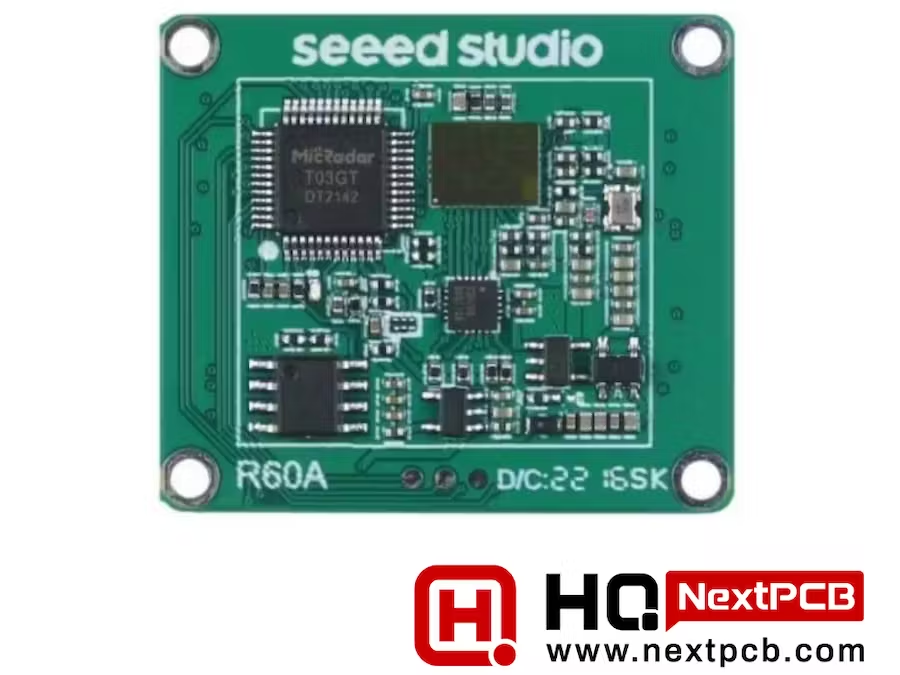
-
The project titled "Ethernet-Enhanced LoRa Gateway: Minimizing Delay, Maximizing Security" focuses on the development of a LoRa (Long Range) gateway with Ethernet connectivity. This gateway serves as a critical link between IoT devices and the internet, providing two key advantages: Low Latency: By utilizing Ethernet, the gateway minimizes data transmission delay, ensuring that IoT data is transmitted quickly and efficiently. This is crucial for real-time or time-sensitive applications. Enhanced Security: The project emphasizes robust security measures to protect IoT data. Ethernet connections can be secured with standard network security protocols, ensuring the integrity and confidentiality of transmitted data. In summary, this project aims to create a high-performance LoRa gateway that optimizes data transfer speed and prioritizes data security, making it ideal for a wide range of IoT applications where low latency and data protection are paramount. In this project, I am creating a LoRa Gateway using Ethernet. The project consists of a LoRa Transmitter and LoRa gateway section. Get PCBs For Your Projects Manufactured You must check out PCBWAY for ordering PCBs online for cheap! You get 10 good-quality PCBs manufactured and shipped to your doorstep for cheap. You will also get a discount on shipping on your first order. Upload your Gerber files onto PCBWAY to get them manufactured with good quality and quick turnaround time. PCBWay now could provide a complete product solution, from design to enclosure production. Check out their online Gerber viewer function. With reward points, you can get free stuff from their gift shop. Also, check out this useful blog on PCBWay Plugin for KiCad from here. Using this plugin, you can directly order PCBs in just one click after completing your design in KiCad. LoRa Transmitter In the transmitter part of the system the following blocks are utilized : Sensor Array: The transmitter is equipped with various sensors, including a temperature sensor(SI7051) for environmental data and accelerometers and gyroscopes(MPU6050) for motion sensing. These sensors continuously collect data. Microcontroller: The microcontroller (XIAO SAMD21)processes the sensor data, monitoring both temperature variations and changes in the device's orientation or position. LoRa Transmitter: Upon detecting a significant change in position, the microcontroller triggers the LoRa transmitter (WIO E5)to send an alert message. This message includes the altered position information and the concurrently recorded temperature data. Power Source: The transmitter operates on a power-efficient setup, utilizing two AA-size batteries that provide power for an extended period, typically lasting several months. The primary purpose of this transmitter is to collect sensor data, detect substantial changes in position, and efficiently transmit alert messages containing both positional and temperature information via LoRa technology. This design ensures long-lasting operation without frequent battery replacements, making it suitable for remote or unattended applications. Block Diagram Of Transmitter Connection Diagram Of The Transmitter Transmitter Part Code #include <Arduino.h> #include <Wire.h> #include "ClosedCube_Si7051.h" #include "MPU6050.h" ClosedCube_Si7051 si7051; MPU6050 accelgyro; #if I2CDEV_IMPLEMENTATION == I2CDEV_ARDUINO_WIRE #include "Wire.h" #endif int data1=0; int data2=0; int data3=0; int data4=0; int16_t ax, ay, az; int16_t gx, gy, gz; #define OUTPUT_READABLE_ACCELGYRO static char recv_buf[512]; static bool is_exist = false; int a_x,a_y,a_z; static int at_send_check_response(char *p_ack, int timeout_ms, char *p_cmd, ...) { int ch = 0; int index = 0; int startMillis = 0; va_list args; memset(recv_buf, 0, sizeof(recv_buf)); va_start(args, p_cmd); Serial1.printf(p_cmd, args); Serial.printf(p_cmd, args); va_end(args); delay(200); startMillis = millis(); if (p_ack == NULL) { return 0; } do { while (Serial1.available() > 0) { ch = Serial1.read(); recv_buf[index++] = ch; Serial.print((char)ch); delay(2); } if (strstr(recv_buf, p_ack) != NULL) { return 1; } } while (millis() - startMillis < timeout_ms); return 0; } static int node_send(uint32_t timeout) { static uint16_t count = 0; int ret = 0; char data[32]; char cmd[128]; memset(data, 0, sizeof(data)); sprintf(data, "%04X,%04X,%04X,%04X", data1, data2, data3,data4); sprintf(cmd, "AT+TEST=TXLRPKT,\"5345454544%s\"\r\n", data); ret = at_send_check_response("TX DONE", 2000, cmd); if (ret == 1) { Serial.print("Sent successfully!\r\n"); } else { Serial.print("Send failed!\r\n"); } data1 = si7051.readTemperature(); data2 = a_z; return ret; } void setup(void) { Serial.begin(115200); si7051.begin(0x40); // default I2C address is 0x40 and 14-bit measurement resolution Serial1.begin(9600); #if I2CDEV_IMPLEMENTATION == I2CDEV_ARDUINO_WIRE Wire.begin(); #elif I2CDEV_IMPLEMENTATION == I2CDEV_BUILTIN_FASTWIRE Fastwire::setup(400, true); #endif accelgyro.initialize(); uint16_t error; char errorMessage[256]; if (at_send_check_response("+AT: OK", 100, "AT\r\n")) { is_exist = true; at_send_check_response("+MODE: TEST", 1000, "AT+MODE=TEST\r\n"); at_send_check_response("+TEST: RFCFG", 1000, "AT+TEST=RFCFG,866,SF12,125,12,15,14,ON,OFF,OFF\r\n"); delay(200); } else { is_exist = false; Serial.print("No E5 module found.\r\n"); } } void loop(void) { accelgyro.getMotion6(&ax, &ay, &az, &gx, &gy, &gz); Serial.print("Sensor data"); Serial.print(ax); Serial.print(","); Serial.print(ay); Serial.print(","); Serial.print(az); Serial.println(); a_x = (ax+ay+az); a_y = sqrt(a_x); a_z = ((az)/ay); Serial.print("x:"); Serial.print(a_z); Serial.println(); if (is_exist) { node_send(2000); delay(500); } } Gateway Using Wiznet W5300 And STM NUCLEO 144 Within the Gateway component, the LoRa receiver efficiently captures incoming data packets. Subsequently, the microcontroller orchestrates intricate data processing operations, encompassing data analysis, transformation, and synthesis. The refined data is then rendered on an OLED Display, a graphical interface for visualizing pertinent information. Simultaneously, a parallel data stream leverages Ethernet connectivity to effectuate the seamless transmission of this processed data to remote Blynk cloud servers. This bidirectional data channel enables real-time data synchronization and remote telemetry visualization via a dedicated Android application. The Android application is endowed with the capability to graphically represent key telemetry metrics, including environmental temperature, precise transmitter geolocation coordinates, the Received Signal Strength Indicator (RSSI), and comprehensive status updates pertaining to both transmitter and receiver connections. In addition to the observational aspect, the Android application provides the user with interactive control capabilities over various appliances interconnected to the Gateway via relay switches. These controls are seamlessly integrated, allowing the user to command and manipulate device states through intuitive in-app buttons. This meticulously engineered technical architecture facilitates robust data processing, transmission, and remote management capabilities, culminating in an immersive user experience characterized by comprehensive data visualization and seamless device control via the Android application. Before Interfacing the Nucleo Boards with the Wiznet ToE W5300 Make Sure the following changes have been applied. The ST-LINK pin configuration had to be modified to address potential interference issues caused by the concurrent use of FMC (Flexible Memory Controller) data pins to control the W5300 integrated within the W5300 TOE Shield and the ST-LINK pins on the STM32 Nucleo-144 board. 1. Remove SB5 and SB6 from the top of the STM32 Nucleo-144 board. 2. When combining the W5300 TOE Shield with the STM32 Nucleo-144 board, establish connections using jumper cables as follows: Connect PC10 on the W5300 TOE Shield to the RX (Receive) pin on the STM32 Nucleo-144 board. Connect PC11 on the W5300 TOE Shield to the TX (Transmit) pin on the STM32 Nucleo-144 board. These connections establish the necessary communication link between the W5300 TOE Shield and the STM32 Nucleo-144 board, allowing data to be exchanged between the two components. Check the link to learn the pin configuration of NUCLEO Boards with Ethernet. https://github.com/ARMmbed/mbed-os/blob/master/targets/TARGET_STM/TARGET_STM32F2/TARGET_STM32F207xG/TARGET_NUCLEO_F207ZG/PinNames.h The provided pin configuration indicates that certain UART (Universal Asynchronous Receiver-Transmitter) interfaces on the Nucleo 144 Boards share connections with the Ethernet hardware. Consequently, both hardware and software aspects must be adapted to accommodate this shared resource configuration. From a hardware perspective, special attention must be given to the physical wiring and connectivity to ensure that both the UART interfaces and Ethernet hardware coexist without conflicts. This may involve the use of multiplexers, level shifters, or other hardware components to manage the shared resources effectively. In the software domain, the firmware and software applications running on the microcontroller should be modified to account for the shared UART and Ethernet resources. This could include implementing protocols or routines that coordinate the usage of these shared resources, preventing contention, and ensuring proper data transfer and communication. Overall, managing shared hardware resources on the Nucleo 144 Boards requires careful consideration and integration at both the hardware and software levels to ensure seamless and reliable operation of both UART and Ethernet functionalities. Pinout Of Wiznet W5300 TOE Shield Step 1: Install Required Arduino Libraries and Boards Files In the Arduino IDE, follow these steps to add an additional board manager URL: 1. Open the Arduino IDE on your computer. 2. Go to the "File" menu. 3. Select "Preferences" from the dropdown menu. 4. In the "Preferences" window, find the "Additional Boards Manager URLs" field. It's usually at the bottom of the window. 5. To add a new URL, click the icon on the right side of the field. It looks like a small button with an arrow pointing to the right. 6. A new window will appear where you can enter the URL. 7. Copy and paste the following URL into this field:https://github.com/stm32duino/BoardManagerFiles/raw/main/package_stmicroelectronics_index.json 8. Click the "OK" button to close the window. 9. Click the "OK" button in the "Preferences" window to save your changes and close it. Now, you have added the STM32 board manager URL, and you can proceed to install STM32 boards through the Arduino IDE's board manager. Step 2: To add the "Ethernet" and "FMC" libraries to your Arduino IDE, follow these steps: Download or clone the library repositories for "Ethernet" and "FMC" from their respective sources (GitHub or other repositories) to your computer. Locate the "libraries" folder within the "Arduino15" directory on your computer. The exact path may vary depending on your PC environment. It's usually in a location similar to this: makefile C:\Users\YOUR_NAME\AppData\Local\Arduino15\libraries Inside the "libraries" folder, create two new folders: one named "Ethernet" and the other named "FMC." Copy the contents of the downloaded or cloned "Ethernet" library repository into the "Ethernet" folder you created in the "libraries" directory. Similarly, copy the contents of the downloaded or cloned "FMC" library repository into the "FMC" folder you created in the "libraries" directory. After copying the library files into their respective folders, you should have a directory structure similar to this: Arduino15/libraries/Ethernet Arduino15/libraries/FMC Close and reopen the Arduino IDE to ensure that it recognizes the newly added libraries. Now, you should be able to use the "Ethernet" and "FMC" libraries in your Arduino sketches for your STM32 project. Step 3: To install the STM32 core library and configure the board settings for your STM32 Nucleo-144 board in the Arduino IDE, follow these steps: 1. Open the Arduino IDE on your computer. 2. In the Arduino IDE, go to the "Tools" menu. 3. Select the "Board" submenu. 4. Choose "Board Manager..." from the submenu. This will open the Arduino Board Manager. 5. In the "Board Manager, " type "STM32" in the search bar to filter the available packages. 6. Look for "STM32 Cores" in the list of available packages. 7. Click the "Install" button next to "STM32 Cores" to start the installation process. 8. Wait for the installation to complete. This might take a few minutes, depending on your internet connection speed. 9. Once the installation is finished, close the Arduino IDE and reopen it to ensure that the STM32 core libraries are properly recognized. 10. To configure the board settings for your STM32 Nucleo-144 board, go to the "Tools" menu again. 11. In the "Board" submenu, select "Nucleo-144" as your target board. With these steps completed, your Arduino IDE should be configured to work with STM32 microcontrollers, and you can select your specific STM32 Nucleo-144 board as the target for your projects. How To Use STM32F207ZG(NUCLEO-F207ZG) with Wiznet ToE 5300 in the Project Given the unavailability of the NUCLEO-F429ZI board, which is officially supported by the Wiznet W5300 library, it's prudent to consider alternative hardware options recommended by Wiznet. Here's a technical approach to finding suitable alternatives: 1. Review Wiznet's Compatibility Documentation: Carefully review Wiznet's official documentation, datasheets, and compatibility guides for the W5300 library. Look for mentions of compatible development boards, microcontrollers, or platforms that are recommended or certified for use with the W5300. 2. Check Microcontroller Compatibility: Verify if other STM32 microcontrollers are compatible with the W5300 library. Explore STM32 datasheets and reference manuals to identify microcontrollers with similar features and pin configurations as the NUCLEO-F429ZI. 3. Evaluate Hardware Availability: Investigate the current availability of alternative STM32 Nucleo boards or development kits that meet the compatibility criteria specified by Wiznet. Look for boards that offer Ethernet connectivity and support for the W5300 library. 4. Consider Evaluation Boards: Examine STM32 evaluation boards or development kits that include Ethernet connectivity. Some of these boards may align with Wiznet's recommendations and can be used as a suitable alternative to the NUCLEO-F429ZI. By following these technical steps, you can make an informed decision regarding alternative hardware that aligns with Wiznet's recommendations and allows you to proceed with your project while ensuring compatibility with the W5300 library. Wiznet W5300 Will work in the below listed Nucleo Boards NUCLEO-F207ZG NUCLEO-F429ZI NUCLEO-F439ZI NUCLEO-F722ZE NUCLEO-F756ZG NUCLEO-F767ZI We need to Add [SRAM Enable] to the config file in order to make Wiznet W5300 Work with STM32F207 Using Arduino Libraries. Open the stm32yyxx_hal_conf.h from the folderC:\Users\scarlet\AppData\Local\Arduino15\packages\STMicroelectronics\hardware\stm32\2.0.0\cores\arduino\stm32\stm32yyxx_hal_conf.h Add The Below line to the Code(Refer to the below-highlighted line to place )#define HAL_SRAM_MODULE_ENABLED Remove the existing FMC directory. C:\Users_YOUR_NAME_\AppData\Local\Arduino15\libraries\FMC Remove the existing FMC init code. C:\Users_YOUR_NAME_\AppData\Local\Arduino15\libraries\Ethernet\w5100.cpp FMC.init(); => //FMC.init(); successfully completed all the necessary configurations to enable the STM32F207 (NUCLEO-F207ZG) development board to operate seamlessly within the Arduino IDE environment. With this setup, we can now engage in advanced technical development, firmware programming, and deployment on the STM32F207 platform using the Arduino framework. In this project, I demonstrate the utilization of STM32F207 and STM32F429-based Nucleo Boards in conjunction with the Wiznet ToE 5300 Ethernet shield. since both boards' pin configurations are the same there are no changes in the Circuit diagram or In the connection diagram. Gateway Block diagram GatewayConnection Diagram Gateway with Relay control using Opto isolators Connection Diagram Picture of Components Used in the Project. STM32F207 (NUCLEO-F207ZG) development board with Wiznet W5300 Code For using STM32F207 (NUCLEO-F207ZG) development board in the project. #define BLYNK_PRINT Serial // Enables Serial Monitor /* Fill in information from Blynk Device Info here */ #define BLYNK_TEMPLATE_ID "XXXXXXXX" #define BLYNK_TEMPLATE_NAME "WIZNET TOE 5300" #define BLYNK_AUTH_TOKEN "XXXXXXXXXXXXXXXXXXXXXXXXXXXXXX" #include <Arduino.h> #include "Ethernet.h" #include "HardwareSerial.h" #include <BlynkSimpleEthernet.h> #include "stm32f2xx_hal_sram.h" #include <Wire.h> #include <Adafruit_GFX.h> #include <Adafruit_SSD1306.h> #define W5x00_INT_Pin GPIO_PIN_8 #define W5x00_INT_GPIO_Port GPIOC #define W5x00_RST_Pin GPIO_PIN_9 #define W5x00_RST_GPIO_Port GPIOC #define SCREEN_WIDTH 128 // OLED display width, in pixels #define SCREEN_HEIGHT 64 // OLED display height, in pixels #define OLED_RESET 4 // Reset pin # (or -1 if sharing Arduino reset pin) Adafruit_SSD1306 display(SCREEN_WIDTH, SCREEN_HEIGHT, &Wire, OLED_RESET); /* Network Info */ #define SERVER_PORT 5000 #define MAX_CLIENT 8 int Relay = PA5; int humidity; HardwareSerial Serial5(UART5); EthernetServer server(SERVER_PORT); EthernetClient clients[MAX_CLIENT]; static char recv_buf[512]; static bool is_exist = false; BlynkTimer timer; WidgetLCD lcd(V4); WidgetLCD lcd2(V5); byte mac[] = { 0xDE, 0xAD, 0xBE, 0xEF, 0xFE, 0xED}; IPAddress ip(192, 168, 137, 111); IPAddress myDns(8, 8, 8, 8); IPAddress gateway(192, 168, 137, 1); IPAddress subnet(255, 255, 255, 0); static void HAL_FSMC_MspInit(void){ GPIO_InitTypeDef GPIO_InitStruct ={0}; __HAL_RCC_GPIOD_CLK_ENABLE(); __HAL_RCC_GPIOE_CLK_ENABLE(); __HAL_RCC_GPIOF_CLK_ENABLE(); GPIO_InitStruct.Pin = GPIO_PIN_0|GPIO_PIN_1|GPIO_PIN_2|GPIO_PIN_3 |GPIO_PIN_4|GPIO_PIN_5|GPIO_PIN_12|GPIO_PIN_13 |GPIO_PIN_14|GPIO_PIN_15; GPIO_InitStruct.Mode = GPIO_MODE_AF_PP; GPIO_InitStruct.Pull = GPIO_NOPULL; GPIO_InitStruct.Speed = GPIO_SPEED_FREQ_VERY_HIGH; GPIO_InitStruct.Alternate = GPIO_AF12_FSMC; HAL_GPIO_Init(GPIOF, &GPIO_InitStruct); GPIO_InitStruct.Pin = GPIO_PIN_7|GPIO_PIN_8|GPIO_PIN_9|GPIO_PIN_10 |GPIO_PIN_11|GPIO_PIN_12|GPIO_PIN_13|GPIO_PIN_14 |GPIO_PIN_15; GPIO_InitStruct.Mode = GPIO_MODE_AF_PP; GPIO_InitStruct.Pull = GPIO_NOPULL; GPIO_InitStruct.Speed = GPIO_SPEED_FREQ_VERY_HIGH; GPIO_InitStruct.Alternate = GPIO_AF12_FSMC; HAL_GPIO_Init(GPIOE, &GPIO_InitStruct); GPIO_InitStruct.Pin = GPIO_PIN_8|GPIO_PIN_9|GPIO_PIN_10|GPIO_PIN_14 |GPIO_PIN_15|GPIO_PIN_0|GPIO_PIN_1|GPIO_PIN_4 |GPIO_PIN_5|GPIO_PIN_7; GPIO_InitStruct.Mode = GPIO_MODE_AF_PP; GPIO_InitStruct.Pull = GPIO_NOPULL; GPIO_InitStruct.Speed = GPIO_SPEED_FREQ_VERY_HIGH; GPIO_InitStruct.Alternate = GPIO_AF12_FSMC; HAL_GPIO_Init(GPIOD, &GPIO_InitStruct); } static void MX_FSMC_Init(void) { FSMC_NORSRAM_TimingTypeDef Timing = {0}; SRAM_HandleTypeDef hsram1; __HAL_RCC_FSMC_CLK_ENABLE(); hsram1.Instance = FSMC_NORSRAM_DEVICE; hsram1.Extended = FSMC_NORSRAM_EXTENDED_DEVICE; /* hsram1.Init */ hsram1.Init.NSBank = FSMC_NORSRAM_BANK1; hsram1.Init.DataAddressMux = FSMC_DATA_ADDRESS_MUX_DISABLE; hsram1.Init.MemoryType = FSMC_MEMORY_TYPE_SRAM; hsram1.Init.MemoryDataWidth = FSMC_NORSRAM_MEM_BUS_WIDTH_16; hsram1.Init.BurstAccessMode = FSMC_BURST_ACCESS_MODE_DISABLE; hsram1.Init.WaitSignalPolarity = FSMC_WAIT_SIGNAL_POLARITY_LOW; hsram1.Init.WrapMode = FSMC_WRAP_MODE_DISABLE; hsram1.Init.WaitSignalActive = FSMC_WAIT_TIMING_BEFORE_WS; hsram1.Init.WriteOperation = FSMC_WRITE_OPERATION_ENABLE; hsram1.Init.WaitSignal = FSMC_WAIT_SIGNAL_DISABLE; hsram1.Init.ExtendedMode = FSMC_EXTENDED_MODE_DISABLE; hsram1.Init.AsynchronousWait = FSMC_ASYNCHRONOUS_WAIT_DISABLE; hsram1.Init.WriteBurst = FSMC_WRITE_BURST_DISABLE; /* Timing */ Timing.AddressSetupTime = 1; Timing.AddressHoldTime = 1; Timing.DataSetupTime = 4; Timing.BusTurnAroundDuration = 0; Timing.CLKDivision = 2; Timing.DataLatency = 2; Timing.AccessMode = FSMC_ACCESS_MODE_A; if (HAL_SRAM_Init(&hsram1, &Timing, NULL) != HAL_OK) { Error_Handler(); } } static int at_send_check_response(char *p_ack, int timeout_ms, char *p_cmd, ...) { int ch = 0; int index = 0; int startMillis = 0; va_list args; memset(recv_buf, 0, sizeof(recv_buf)); va_start(args, p_cmd); Serial5.printf(p_cmd, args); Serial.printf(p_cmd, args); va_end(args); delay(200); startMillis = millis(); if (p_ack == NULL) { return 0; } do { while (Serial5.available() > 0) { ch = Serial5.read(); recv_buf[index++] = ch; Serial.print((char)ch); delay(2); } if (strstr(recv_buf, p_ack) != NULL) { return 1; } } while (millis() - startMillis < timeout_ms); return 0; } //////////////////////////////////////////////////////////////////// static int recv_prase(void) { char ch; int index = 0; memset(recv_buf, 0, sizeof(recv_buf)); while (Serial5.available() > 0) { ch = Serial5.read(); recv_buf[index++] = ch; Serial.print((char)ch); delay(2); } if (index) { char *p_start = NULL; char data[32] = { 0, }; int rssi = 0; int snr = 0; p_start = strstr(recv_buf, "+TEST: RX \"5345454544"); if (p_start) { p_start = strstr(recv_buf, "5345454544"); if (p_start && (1 == sscanf(p_start, "5345454544%s,", data))) { display.clearDisplay(); display.setCursor(0,0); display.print("Transmitter found"); display.display(); data[16] = 0; int data1,data2,data3,data4; char *endptr,*endptr1,*endpt2,*endptr3; char dataarray1[5] = {data[0], data[1],data[2], data[3]}; char dataarray2[5] = {data[4], data[5], data[6], data[7]}; char dataarray3[5] = {data[8], data[9], data[10], data[11]}; char dataarray4[5] = {data[12], data[13],data[14], data[15]}; data1 = strtol(dataarray1, &endptr, 16); data2 = strtol(dataarray2, &endptr1, 16); data3 = strtol(dataarray3, &endptr, 16); data4 = strtol(dataarray4, &endptr1, 16); lcd2.clear(); Serial.print("data1:"); Serial.print(data1); Serial.println(); Serial.print("data2:"); Serial.print(data2); Serial.println(); Serial.print("data3:"); Serial.print(data3); Serial.println(); Serial.print("data received displaying on the wio terminal"); Serial.print("\r\n"); Blynk.virtualWrite(V2,data1); display.setCursor(0, 20); display.print("Temperature:"); display.print(data1); display.print(" C"); humidity = 0.5 * (data1 + 25); Blynk.virtualWrite(V3,humidity); display.setCursor(0, 30); display.print("Humidity:"); display.print(humidity ); display.print("%"); if(data2 <=10) { display.setCursor(0,45); display.print("The device Position had Changed"); lcd.clear(); //Use it to clear the LCD Widget lcd.print(0, 0, "The device Posi"); // use: (position X: 0-15, position Y: 0-1, "Message you want to print") lcd.print(0, 1, "tion had Changed"); // use: (position X: 0-15, position Y: 0-1, "Message you want to print") } else { display.setCursor(0,45); display.print("The device is in a constant position"); lcd.clear(); //Use it to clear the LCD Widget lcd.print(0, 0, "The device is in"); // use: (position X: 0-15, position Y: 0-1, "Message you want to print") lcd.print(0, 1, "constant position"); // use: (position X: 0-15, position Y: 0-1, "Message you want to print") } } p_start = strstr(recv_buf, "RSSI:"); if (p_start && (1 == sscanf(p_start, "RSSI:%d,", &rssi))) { String newrssi = String(rssi); Serial.print(rssi); Serial.print("\r\n"); Blynk.virtualWrite(V6,newrssi); display.setCursor(0,10); display.print("RSSI:"); display.print(rssi); display.print(" dB"); display.display(); } p_start = strstr(recv_buf, "SNR:"); if (p_start && (1 == sscanf(p_start, "SNR:%d", &snr))) { Serial.print(snr); Serial.print("\r\n"); } return 1; } } return 0; } ///////////////////////////////////////////////////////////////////////////// static int node_recv(uint32_t timeout_ms) { at_send_check_response("+TEST: RXLRPKT", 1000, "AT+TEST=RXLRPKT\r\n"); int startMillis = millis(); do { if (recv_prase()) { return 1; } } while (millis() - startMillis < timeout_ms); Serial.print("Transmitter Not Found"); Serial.println(""); display.clearDisplay(); display.setCursor(0,0); display.print("Transmitter Not Found"); display.display(); lcd.clear(); lcd2.clear(); //Use it to clear the LCD Widget lcd2.print(0, 0, "Transmitter"); // use: (position X: 0-15, position Y: 0-1, "Message you want to print") lcd2.print(0, 1, "Disconnected"); // use: (position X: 0-15, position Y: 0-1, "Message you want to print") display.clearDisplay(); return 0; } //////////////////////////// BLYNK_WRITE(V0) { int x = param.asInt(); Serial.println(x); if(x == 1) { digitalWrite(Relay,HIGH); display.clearDisplay(); display.setCursor(0,20); display.print("LED ON"); display.display(); } else { digitalWrite(Relay,LOW); display.clearDisplay(); display.setCursor(0,20); display.print("LED OFF"); display.display(); }} void setup() { MX_FSMC_Init(); HAL_FSMC_MspInit(); Serial3.setRx(PC11); Serial3.setTx(PC10); Serial3.begin(9600); Serial5.begin(9600); pinMode(Relay,OUTPUT); Ethernet.begin(mac, ip, myDns, gateway, subnet); Blynk.begin(BLYNK_AUTH_TOKEN); if(!display.begin(SSD1306_SWITCHCAPVCC, 0x3C)) { Serial.println(F("SSD1306 allocation failed")); for(;;); } display.display(); delay(2000); // Pause for 2 seconds if (at_send_check_response("+AT: OK", 100, "AT\r\n")) { is_exist = true; at_send_check_response("+MODE: TEST", 1000, "AT+MODE=TEST\r\n"); at_send_check_response("+TEST: RFCFG", 1000, "AT+TEST=RFCFG,866,SF12,125,12,15,14,ON,OFF,OFF\r\n"); delay(200); } else { is_exist = false; Serial.print("No Serial5 module found.\r\n"); display.setTextSize(1); // Normal 1:1 pixel scale display.setTextColor(SSD1306_WHITE); // Draw white text display.setCursor(0,0); // Start at top-left corner display.println(F("LoRa Device Not Found")); display.display(); } display.clearDisplay(); display.setTextSize(1); // Normal 1:1 pixel scale display.setTextColor(SSD1306_WHITE); // Draw white text display.setCursor(0,0); // Start at top-left corner display.print("IP:"); display.print(ip); display.display(); delay(1000); display.clearDisplay(); } void loop() { display.clearDisplay(); if (is_exist) { node_recv(2000); } timer.run(); Blynk.run(); } STM32F429 (NUCLEO-F429zi) development board with Wiznet W5300 Incorporating the NUCLEO-F429ZI within an Arduino environment does not necessitate alterations to the Wiznet libraries provided. The procedure chiefly involves the following technical steps: 1. Library Integration: The Wiznet libraries, unaltered, are seamlessly assimilated into the Arduino libraries directory, permitting immediate utilization within the Arduino Integrated Development Environment (IDE). 2. Essential Arduino Libraries: Concurrently, essential Arduino libraries germane to the project's requisites are installed to complement the Wiznet libraries. These supplementary libraries may encompass sensor drivers, OLED display routines, or other components imperative to the application. 3. Board Configuration: Configuration of the Arduino IDE involves the precise specification of the NUCLEO-F429ZI board variant. This necessitates the installation of pertinent board files, typically performed by introducing the board's JSON configuration into the Arduino Board Manager. 4. IDE Setup: Within the Arduino IDE, meticulous attention is afforded to board selection, COM port designation, and other parameters vital for compatibility with the NUCLEO-F429ZI board. 5. Code Development: Arduino sketches, thoughtfully architected, are crafted, employing the functions and capabilities afforded by the Wiznet libraries, unadulterated. These sketches are subsequently uploaded to the NUCLEO-F429ZI board for execution. By meticulously executing these technical maneuvers, a seamless amalgamation of the NUCLEO-F429ZI board into the Arduino environment is achieved, obviating the need for direct alterations to the provided Wiznet libraries. This methodology fosters expedited development and assures steadfast compatibility with the Arduino IDE. Code For using STM32F429 (NUCLEO-F429zi) development board in the project. #define BLYNK_PRINT Serial // Enables Serial Monitor /* Fill in information from Blynk Device Info here */ #define BLYNK_TEMPLATE_ID "xxxxxxxxxxxxxx" #define BLYNK_TEMPLATE_NAME "WIZNET TOE 5300" #define BLYNK_AUTH_TOKEN "xxxxxxxxxxxxxxxxxxxxxxxxxxxxxx" #include <Arduino.h> #include "Ethernet.h" #include "HardwareSerial.h" #include <BlynkSimpleEthernet.h> #include <Wire.h> #include <Adafruit_GFX.h> #include <Adafruit_SSD1306.h> #define SCREEN_WIDTH 128 // OLED display width, in pixels #define SCREEN_HEIGHT 64 // OLED display height, in pixels #define OLED_RESET 4 // Reset pin # (or -1 if sharing Arduino reset pin) Adafruit_SSD1306 display(SCREEN_WIDTH, SCREEN_HEIGHT, &Wire, OLED_RESET); int Relay1= PA5; int humidity; HardwareSerial Serial5(UART5); static char recv_buf[512]; static bool is_exist = false; BlynkTimer timer; WidgetLCD lcd(V4); WidgetLCD lcd2(V5); static int at_send_check_response(char *p_ack, int timeout_ms, char *p_cmd, ...) { int ch = 0; int index = 0; int startMillis = 0; va_list args; memset(recv_buf, 0, sizeof(recv_buf)); va_start(args, p_cmd); Serial5.printf(p_cmd, args); Serial.printf(p_cmd, args); va_end(args); delay(200); startMillis = millis(); if (p_ack == NULL) { return 0; } do { while (Serial5.available() > 0) { ch = Serial5.read(); recv_buf[index++] = ch; Serial.print((char)ch); delay(2); } if (strstr(recv_buf, p_ack) != NULL) { return 1; } } while (millis() - startMillis < timeout_ms); return 0; } //////////////////////////////////////////////////////////////////// static int recv_prase(void) { char ch; int index = 0; memset(recv_buf, 0, sizeof(recv_buf)); while (Serial5.available() > 0) { ch = Serial5.read(); recv_buf[index++] = ch; Serial.print((char)ch); delay(2); } if (index) { char *p_start = NULL; char data[32] = { 0, }; int rssi = 0; int snr = 0; p_start = strstr(recv_buf, "+TEST: RX \"5345454544"); if (p_start) { p_start = strstr(recv_buf, "5345454544"); if (p_start && (1 == sscanf(p_start, "5345454544%s,", data))) { display.clearDisplay(); display.setCursor(0,0); display.print("Transmitter found"); display.display(); data[16] = 0; int data1,data2,data3,data4; char *endptr,*endptr1,*endpt2,*endptr3; char dataarray1[5] = {data[0], data[1],data[2], data[3]}; char dataarray2[5] = {data[4], data[5], data[6], data[7]}; char dataarray3[5] = {data[8], data[9], data[10], data[11]}; char dataarray4[5] = {data[12], data[13],data[14], data[15]}; data1 = strtol(dataarray1, &endptr, 16); data2 = strtol(dataarray2, &endptr1, 16); data3 = strtol(dataarray3, &endptr, 16); data4 = strtol(dataarray4, &endptr1, 16); lcd2.clear(); Serial.print("data1:"); Serial.print(data1); Serial.println(); Serial.print("data2:"); Serial.print(data2); Serial.println(); Serial.print("data3:"); Serial.print(data3); Serial.println(); Serial.print("data received displaying on the wio terminal"); Serial.print("\r\n"); Blynk.virtualWrite(V2,data1); display.setCursor(0, 20); display.print("Temperature:"); display.print(data1); display.print(" C"); humidity = 0.5 * (data1 + 25); Blynk.virtualWrite(V3,humidity); display.setCursor(0, 30); display.print("Humidity:"); display.print(humidity ); display.print("%"); if(data2 <=10) { display.setCursor(0,45); display.print("The device Position had Changed"); lcd.clear(); //Use it to clear the LCD Widget lcd.print(0, 0, "The device Posi"); // use: (position X: 0-15, position Y: 0-1, "Message you want to print") lcd.print(0, 1, "tion had Changed"); // use: (position X: 0-15, position Y: 0-1, "Message you want to print") } else { display.setCursor(0,45); display.print("The device is in a constant position"); lcd.clear(); //Use it to clear the LCD Widget lcd.print(0, 0, "The device is in"); // use: (position X: 0-15, position Y: 0-1, "Message you want to print") lcd.print(0, 1, "constant position"); // use: (position X: 0-15, position Y: 0-1, "Message you want to print") } } p_start = strstr(recv_buf, "RSSI:"); if (p_start && (1 == sscanf(p_start, "RSSI:%d,", &rssi))) { String newrssi = String(rssi); Serial.print(rssi); Serial.print("\r\n"); Blynk.virtualWrite(V6,newrssi); display.setCursor(0,10); display.print("RSSI:"); display.print(rssi); display.print(" dB"); display.display(); } p_start = strstr(recv_buf, "SNR:"); if (p_start && (1 == sscanf(p_start, "SNR:%d", &snr))) { Serial.print(snr); Serial.print("\r\n"); } return 1; } } return 0; } ///////////////////////////////////////////////////////////////////////////// static int node_recv(uint32_t timeout_ms) { at_send_check_response("+TEST: RXLRPKT", 1000, "AT+TEST=RXLRPKT\r\n"); int startMillis = millis(); do { if (recv_prase()) { return 1; } } while (millis() - startMillis < timeout_ms); Serial.print("Transmitter Not Found"); Serial.println(""); display.clearDisplay(); display.setCursor(0,0); display.print("Transmitter Not Found"); display.display(); lcd.clear(); lcd2.clear(); //Use it to clear the LCD Widget lcd2.print(0, 0, "Transmitter"); // use: (position X: 0-15, position Y: 0-1, "Message you want to print") lcd2.print(0, 1, "Disconnected"); // use: (position X: 0-15, position Y: 0-1, "Message you want to print") display.clearDisplay(); return 0; } //////////////////////////// BLYNK_WRITE(V0) { int x = param.asInt(); Serial.println(x); if(x == 1) { digitalWrite(Relay1,HIGH); display.clearDisplay(); display.setCursor(0,20); display.print("LED ON"); display.display(); } else { digitalWrite(Relay1,LOW); display.clearDisplay(); display.setCursor(0,20); display.print("LED OFF"); display.display(); }} void setup() { Serial3.setRx(PC11); Serial3.setTx(PC10); Serial3.begin(9600); Serial5.begin(9600); pinMode(Relay1,OUTPUT); Blynk.begin(BLYNK_AUTH_TOKEN); if(!display.begin(SSD1306_SWITCHCAPVCC, 0x3C)) { Serial.println(F("SSD1306 allocation failed")); for(;;); } display.display(); delay(2000); // Pause for 2 seconds if (at_send_check_response("+AT: OK", 100, "AT\r\n")) { is_exist = true; at_send_check_response("+MODE: TEST", 1000, "AT+MODE=TEST\r\n"); at_send_check_response("+TEST: RFCFG", 1000, "AT+TEST=RFCFG,866,SF12,125,12,15,14,ON,OFF,OFF\r\n"); delay(200); } else { is_exist = false; Serial.print("No Serial5 module found.\r\n"); display.setTextSize(1); // Normal 1:1 pixel scale display.setTextColor(SSD1306_WHITE); // Draw white text display.setCursor(0,0); // Start at top-left corner display.println(F("LoRa Device Not Found")); display.display(); } display.clearDisplay(); display.setTextSize(1); // Normal 1:1 pixel scale display.setTextColor(SSD1306_WHITE); // Draw white text display.setCursor(0,0); // Start at top-left corner display.println("Device Initialized"); display.println("sucessfully"); display.display(); delay(1000); display.clearDisplay(); } void loop() { display.clearDisplay(); if (is_exist) { node_recv(2000); } timer.run(); Blynk.run(); } Project Output Pictures Serial Output Images Project Video Conclusion In conclusion, the Wiznet W5300 stands out as an exceptionally straightforward and versatile component for seamless integration into diverse IoT applications, characterized by its robust security capabilities and ultra-low latency performance. W5300 serves as a pivotal enabler for the enhancement of pre-existing projects into IoT-ready solutions, effectively optimizing the Bill of Materials (BOM) cost efficiency. The W5300 empowers developers with a comprehensive set of advanced networking features, including but not limited to: 1. Security Paradigm: The W5300 architecture encompasses an array of advanced security protocols and mechanisms, ensuring data integrity, confidentiality, and authenticity throughout the network communication process. These mechanisms encompass SSL/TLS encryption, secure bootstrapping, and robust firewall configurations, fortifying IoT ecosystems against potential threats. 2. Latency Minimization: W5300 demonstrates a superlative capability for mitigating communication latency. With its streamlined data transmission pathways, optimized protocol stacks, and efficient hardware processing, the module substantially minimizes the time-to-data delivery, thereby accommodating stringent real-time IoT requirements. 3. IoT Augmentation: W5300 serves as a pivotal tool for the augmentation of conventional, non-IoT projects. By seamlessly integrating W5300 into existing setups, developers can elevate these systems into the realm of IoT without incurring exorbitant BOM costs. This transformation encompasses the facilitation of remote monitoring, data acquisition, and IoT-enabled control paradigms. Incorporating W5300 into IoT endeavors extends the capabilities of developers, permitting them to address sophisticated technical challenges and engineer IoT solutions that are both secure and responsive to real-time demands.