Search the Community
Showing results for tags 'bluetooth'.
Found 5 results
-
 In this article, will see how we can integrate the Beetle ESP32 C3 with home assistance. Beetle ESP32 C3 The Beetle ESP32-C3 is based on the ESP32-C3, a RISC-V 32-bit single-core processor. Despite its tiny size (only 25×20.5 mm), it packs a punch with up to 13 IO ports broken out, making it ideal for various projects without worrying about running out of IO options. Key Features: Ultra-Small Size: The Beetle ESP32-C3 measures just 25×20.5 mm (0.98×0.81 inch), making it perfect for space-constrained projects. Built-in Lithium Battery Charging Management: Safely charge and discharge lithium-ion batteries directly on the board. No need for additional modules, to ensure application size and safety. Easy Screen Connectivity: The matching bottom plate simplifies project assembly and screen usage. Dual-Mode Communication: Supports Wi-Fi and Bluetooth 5 (LE). Reduces networking complexity. Compatible with both Bluetooth Mesh and Espressif WiFi Mesh for stable communication and extended coverage. Get PCBs for Your Projects Manufactured You must check out PCBWAY for ordering PCBs online for cheap! You get 10 good-quality PCBs manufactured and shipped to your doorstep for cheap. You will also get a discount on shipping on your first order. Upload your Gerber files onto PCBWAY to get them manufactured with good quality and quick turnaround time. PCBWay now could provide a complete product solution, from design to enclosure production. Check out their online Gerber viewer function. With reward points, you can get free stuff from their gift shop. Also, check out this useful blog on PCBWay Plugin for KiCad from here. Using this plugin, you can directly order PCBs in just one click after completing your design in KiCad. Installing ESP Addon in Home Assistance First, we need to add the ESP addon to our Home Assistance system. Open the home assistance. Next, navigate to the settings and open the add-ons. Here selects ESP home and install it. Then open the web ui. ESPHome on the Beetle ESP32 C3 ESPHome is an open-source firmware that allows you to configure and manage your ESP devices easily. Open the ESP home web UI and add a new device. Then open the ESPHOME web and follow the instructions to flash ESP Home firmware. Next, connect Beetle to the PC and select then burn. Wait until it finishes. Next, enter the WiFi credentials to configure with WiFi. Then click visit device, you can see this kind of web page. Connecting Beetle ESP32 C3 to Home Assistant Once your FireBeetle ESP32 C3 is online with the ESPHome firmware, Home Assistant will automatically discover it. You can see the device under the settings menu. Next, open the ESP home and add a new device Then enter all the details, and next select the wireless option. You can see the device status as Online. Here you can edit the beetle behavior. Controlling Devices and Automation With the Beetle ESP32 C3 integrated into Home Assistant, you can: Control smart switches, lights, or other devices connected to your Beetle. Set up automation based on sensor data (e.g., turn on lights when motion is detected). Monitor temperature, humidity, and other environmental factors using Beetle sensors. With the Beetle ESP32 C3 integrated into Home Assistant, you can: Control smart switches, lights, or other devices connected to your Beetle. Set up automation based on sensor data (e.g., turn on lights when motion is detected). Here is the simple code snippet to control the onboard LED on the Beetle. switch: - platform: gpio name: "test_lights Onboard light" pin: 10 inverted: True restore_mode: RESTORE_DEFAULT_OFF Here is the complete sketch. Then install it. Next, open the devices again and select the esp home. Here you will see your device details and it will show the switch status. From here you can control the onboard LED. Troubleshooting and Tips If you encounter issues: Check your ESPHome configuration for errors. Verify that your Beetle ESP32 C3 is connected to the correct Wi-Fi network. Use Home Assistant’s logs and developer tools to debug any problems. Conclusion Integrating the Beetle ESP32 C3 with Home Assistant expands your smart home capabilities. Whether you’re building custom sensors, controlling lights, or automating tasks, this combination empowers you to create a personalized and efficient home environment. Happy tinkering! 🏡🔌
 -
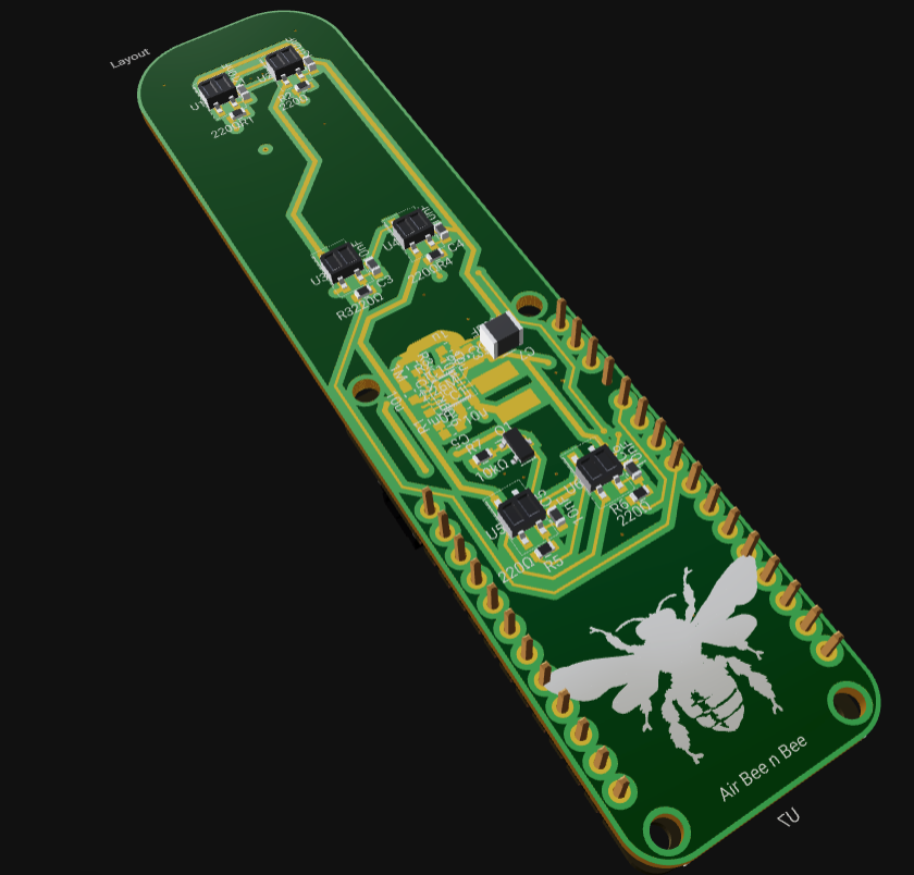
 One of my teammates is working on an open Hardware Project that I thought to share. The product they’re developing is a bee hotel for native bees (not honeybees)! At the SF Climate hackathon, they integrated the Particle Argon onto a PCB with solar panels, MPPC, and a PWM PIR sensor for the bees. Here’s the link to the schematics, layout and 3D. I'll add a 3D screenshot at the bottom of the post. "A little bit of background, a native bee hotel houses sedentary bees which lay their eggs in tube structures, like hollow plant stems. We want to use PIR sensors along the tubes to get bee traffic data and build a country-wide bee traffic map. Solar Cells I’ve bumped into the IXYS KXOB25 series before and loved them for their reflowability. I wanted to connect them in parallel so the only constraint was that their output voltage is less than 5V, which is the maximum input voltage of the energy harvesting IC. Energy Harvesting I chose the LTC3105EDD 15 because I’ve seen it used to maximize solar cell power output in some nanosatellite projects I’ve browsed in the past. Although it doesn’t have an actual MPPT algorithm, it has a very attractive 250mV startup voltage which can potentially increase the times of day our device will provide power (dawn, dusk, cloud cover). All this needs real world testing which is coming next week. PIR Sensors These are paired infrared transmitters and receivers. As seen in the 3D view, we’re using 2 of them per bee tube to determine which direction the bees are going (in or out of the tube). Of course, this would need to be done in firmware. To save power (because these PIR diodes are super power hungry, we added a low side MOSFET that switches all three strings of PIR diodes (they are strung in series to get 1.1V drive from a 3.3V source). In theory, we can decrease the PWM duty cycle to as low as the PIR’s rise time and set the frequency to 1Hz which would save so much power. Future Steps Here are the unknowns that we’ll be researching. I already see some good answers in the forums, but please feel free to chime in! I’ve played with Edge Impulse in the past and we want to run a small tflite model on particle hardware that would determine what type of bee is in the hotel based on a short audio sample. We also want to send this data to a central server hosted by particle; in your experience how many weeks/months would it take to setup particle cloud to get up to 100 provisioned devices sending about 50 bytes of data to a central server? It would be awesome if we can get that done quickly."
-
 Materials AmebaD [RTL8722 CSM/DM] x 2 Example Introduction BLE connections use a server client model. The server contains the data of interest, while the client connects to the server to read the data. Commonly, a Bluetooth peripheral device acts as a server, while a Bluetooth central device acts as a client. Servers can contain many services, with each service containing a some set of data. Clients can send requests to read or write some data and can also subscribe to notifications so that the server can send data updates to a client. In this example, a basic battery client is set up on the Ameba Bluetooth stack. The client connects to another Ameba board running the corresponding BLE battery service to read the battery level data. Procedure On the first Ameba board, upload the BLEBatteryService example code and let it run. For the second Ameba board, open the example “Files” -> “Examples” -> “AmebaBLE” -> “BLEBatteryClient”. Upload the code and press the reset button on Ameba once the upload is finished. Open the serial monitor and observe the log messages as the Ameba board with the battery client scans, connects, and reads data from the Ameba board with the battery service. Highlighted in yellow, the Ameba board with the battery client first scans for advertising BLE devices with the advertised device name “AMEBA_BLE_DEV” and the advertised service UUID of 0x180F representing the battery service. After finding the target device, the Ameba board with the battery client forms a BLE connection and searches for a battery service on the connected device, highlighted in blue. With the client connected to the service, the battery client begins to read data using both regular data reads and notifications, highlighted in green. Code Reference BLEClient is used to create a client object to discover services and characteristics on the connected device. setNotifyCallback() is used to register a function that will be called when a battery level notification is received. BLE.configClient() is used to configure the Bluetooth stack for client operation. addClient(connID) creates a new BLEClient object that corresponds to the connected device. For more resources: If you need additional technical documents or the source code for this project. Please visit the official websites and join the Facebook group and forum. Ameba Official Website: https://www.amebaiot.com/en/ Ameba Facebook Group: https://www.facebook.com/groups/amebaioten Ameba Forum: https://forum.amebaiot.com/
 -
A BLE beacon broadcasts its identity to nearby Bluetooth devices, to enable the other devices to determine their location relative to the beacon, and to perform actions based on information broadcast by the beacon. Example applications of beacons include indoor positioning system, location-based advertising and more. From the definition of its purpose as a broadcast device, a BLE beacon thus cannot be connected to, and can only send information in its Bluetooth advertisement packets. There are several BLE beacon protocols. The Ameba BLEBeacon library supports the iBeacon and AltBeacon protocols.
-
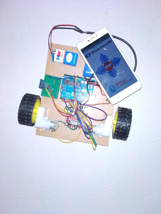
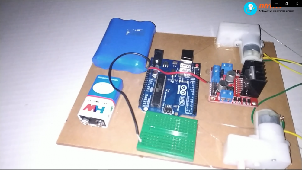
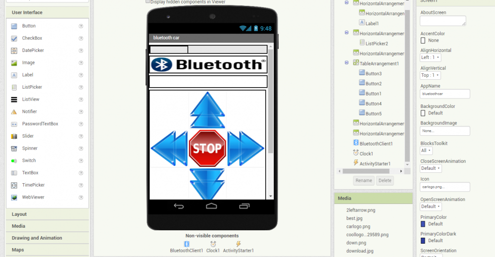
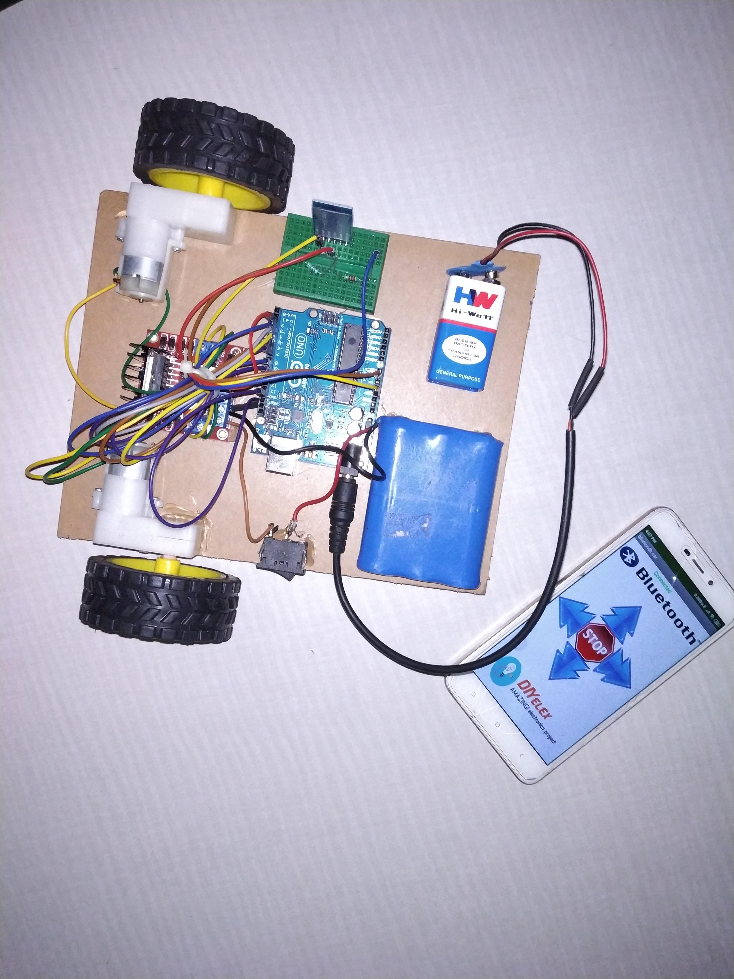
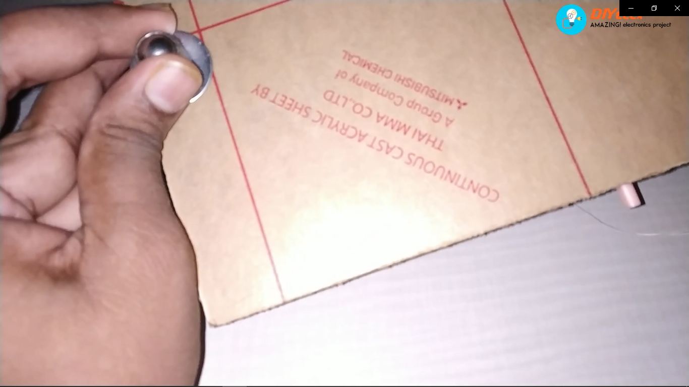
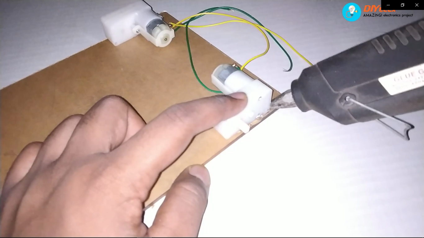
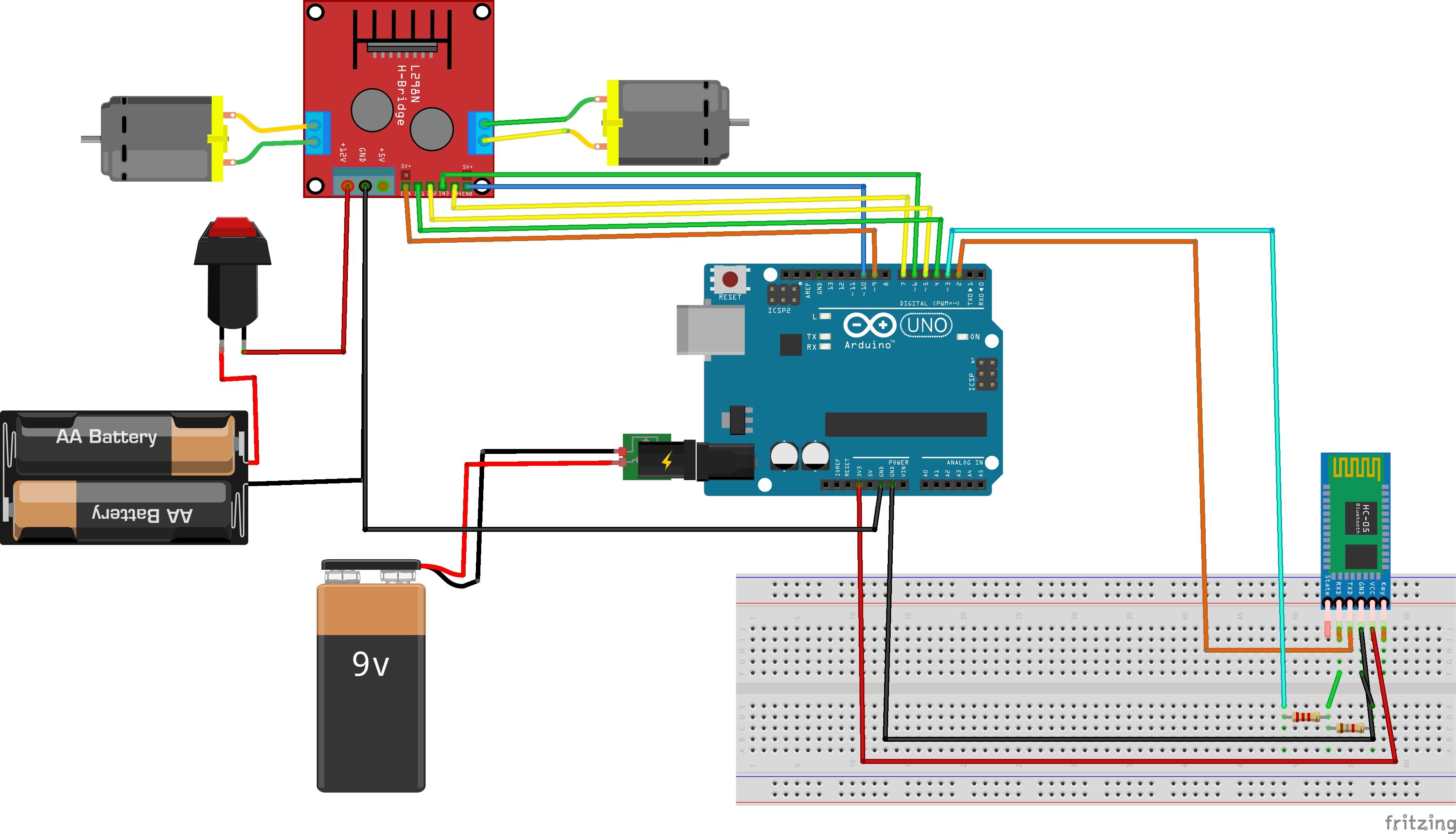
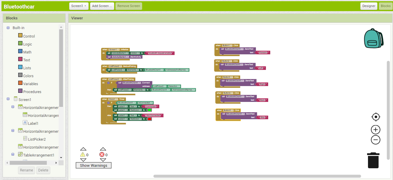
I have just started with the youtube channel, so I decided to make a Bluetooth controlled robotic car. As am an electronics engineer I have knowledge about electronics. but I don't know how to build a custom android application. so Before making the project I learn about MIT app inventor and try to make one app which was a great success it is quite easy to do. In this article, we will learn how to make a custom Android application and how to configure the Bluetooth module with Arduino. Hardware requirements: Arduino Uno Bluetooth HC-05 l298n motor Driver acrylic sheet wheels x2 geared dc motor x2 mini breadboard 4.7k, 2.2k resistor jumper wires 12v battery 9v battery switch Step 1: Building Chassis I used an acrylic sheet length of 18cm and width of 13cm. First, I positioned all parts that going to be mounted on the chassis. then I used a hot glue gun to stick the parts to acrylic you can use spacers or screws. after mounting all parts I stick the caster wheel at the bottom of the chassis. Step 2: Connection Make the connection according to the circuit diagram. we can use separate power for Arduino. Motor driver and 12v battery connected through the switch. As we can see in the circuit diagram there is 2.2k and 4.7 k resistor connected to the pins of the bluetooth module. the main reason for this is the HC-05 Bluetooth module uses a logic level of 3.3v. While transmitting data from HC-05 to Arduino there is no problem because Arduino is capable of receiving data from 3.3v logic, but while receiving any data from Arduino to HC-05 Arduino uses 5v logic which may damage our Bluetooth module, to convert 5v logic level to 3.3v we use a voltage divider method. Make sure that there is common ground between motor driver and Arduino otherwise motor not work. Step 3: Programming /* Author:DIYelex date: 3/8/2019 */ #include <SoftwareSerial.h> // TX RX software library for bluetooth SoftwareSerial mySerial(2, 3); // Connect the TXD pin of BT module to pin 2 of the Arduino and the RXD pin of BT module to pin 3 of Arduino. int Rightmotor1 = 4; //pin 1 of Rightmotor int Rightmotor2 = 5; //pin2 of Rightmotor int leftmotor1 = 6;//pin1 of leftmotor int leftmotor2 = 7;//pin2 of leftmotor int en1=9; //enable pin for Rightmotor int en2=10; // enable pin for leftmotor String readString; void setup() { pinMode(Rightmotor1,OUTPUT); // attach Right Motor 1st wire to pin 4 pinMode(Rightmotor2,OUTPUT); // attach Right Motor 1st wire to pin 5 pinMode(leftmotor1,OUTPUT);// attach Right Motor 1st wire to pin 6 pinMode(leftmotor2,OUTPUT);// attach Right Motor 1st wire to pin 7 pinMode(en1,OUTPUT); //attach motor drivers rightmotor enable pin to PWM pin 9 of arduino pinMode(en2,OUTPUT);//attach motor drivers leftmotor enable pin to PWM pin 10 of arduino Serial.begin(9600); //Setup usb serial connection to computer mySerial.begin(9600);//Setup Bluetooth serial connection to android } void loop() { while(mySerial.available()){ delay(50); char data = mySerial.read();//store the data come from bluetooth to char data readString+=data; } if(readString.length() > 0) { Serial.println(readString); ///Print the data to serial monitor which is given by bluetooth if(readString == "Forward"){ //if forward received do following digitalWrite(Rightmotor1, HIGH); ////////////FORWARD //////////////////////// digitalWrite(Rightmotor2, LOW); digitalWrite(leftmotor1, HIGH); digitalWrite(leftmotor2, LOW); analogWrite(en1,200);// for controlling speed of Rightmotor vary the value from 0 to 255 analogWrite(en2,200);// for controlling speed of leftmotor vary the value from 0 to 255 } if(readString == "Back"){ //if Back received do following digitalWrite(Rightmotor1, LOW); ////////////BACK///////////////////////////// digitalWrite(Rightmotor2, HIGH); digitalWrite(leftmotor1, LOW); digitalWrite(leftmotor2, HIGH); analogWrite(en1,200); analogWrite(en2,200); } if(readString == "Left"){ //if left received do following digitalWrite(Rightmotor1, HIGH);/////////////LEFT//////////////////////////// digitalWrite(Rightmotor2, LOW); digitalWrite(leftmotor1, LOW); digitalWrite(leftmotor2, HIGH); analogWrite(en1,80); analogWrite(en2,80); } if(readString == "Right"){ //if Right received do following digitalWrite(Rightmotor1, LOW);/////////////RIGHT//////////////////////// digitalWrite(Rightmotor2, HIGH); digitalWrite(leftmotor1, HIGH); digitalWrite(leftmotor2, LOW); analogWrite(en1,80); analogWrite(en2,80); } if(readString == "Stop"){ //if stop received do following digitalWrite(Rightmotor1, LOW); ///////////stop///////////////// digitalWrite(Rightmotor2, LOW); digitalWrite(leftmotor1, LOW); digitalWrite(leftmotor2, LOW); } readString = ""; } } Step 4: Android App Now we have to build Bluetooth applications that would be capable of controlling your robot car. If you wish to download my application you can download it from github: The Bluetooth car How I created this application was through App Inventor 2, The images above show both the "Designer" & "Block" view of my application so you can build and change thing up if you wish! Steps for configuring bluetooth First turn on the switch of robot car Go to setting Click on the Bluetooth TabTurn Bluetooth on Wait for your phone to find the HC-05 Bluetooth module Once it has been found click it and input the password by default it should be either "1234" or "0000" Now open the application Bluetooth car Application and click the " Bluetooth image" button You should see the HC-05 Module (If not re-try the steps above) click on the Module The Application will then return automatically to the main screen and you can see the green text "connected" At this point, the HC-05 Modules Red LED should now be constantly on instead of pulsing meaning a device is currently connected. Conclusion Thanks for Reading watch this project video on youtube https://youtu.be/iC7P9nyFu9I