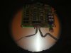
Chess computer power supply.

Mart

Sep 16, 2011
13
Joined
Sep 16, 2011
Messages
13
Hello folks I have an old chess computer that I have lost the power supply for, I intially thought it would be straight forward enough to find a replacement but not so.
The original specifications are as follows.

Input: 240 VAC 60 Hz, 30 watt
Output: 6 VAC @ 1.7 Amps / 12 VAC @ 1.7 Amps
Originally intended for Milton Bradley Games. The enclosure and the 6 ft. cord are black.
Output cord has 3-pin overmolded connector.


The computer connection does have a 3 core input of red, yellow and black wires. The red goes straight to the motherboard on to terminal 1 on the P1 connector block and the black and yellow go to the switch which has a 24v ceramic capacitor soldered between the 2 terminals and then after the switch to terminals 2 and 3 respectively on the same P1 connector block as the red wire went to.
I think it will be a dual output supply giving 6 VAC, 12 VAC and 0 Volts but I am not sure which wires are doing what.
Would it be possible in the event of not being able to source a power supply to match the original spec to rewire the incoming to use 2 supplies, one 6 VAC & one 12 VAC ?.
Any help would be much appreciated. Thanks.
 
Last edited:

davelectronic

Dec 13, 2010
1,087
Joined
Dec 13, 2010
Messages
1,087
Chess power supply

Hi Mart.
Yes its possible to make a supply for it with split rails 12 volts + and 6 volts + are you sure the input is AC as often its DC on these game electronics, can you post a clear picture of the unit and power socket.

The stumbling block might be the connector, as some manufacturers come up with a one off power socket plug design, but it might be easy plug to find, or you have a power lead and line plug or socket on it.

Another consideration is cost, i usually opt for stuff thats not costly, or press another piece of hardware into use for saving and convenience, one of the moddings that came to mind was an artical on an Xbox 360, the owners power supply died, so he modded an old atx pc power supply, as i said some if not most will run happily on DC, the only exception to this rule is DC psu input generally wont run on AC.

A look at the unit, will further the way to go, there not huge currents, and there will be some tolerance leeway in voltage i expect. Dave. :)
 

daddles

Jun 10, 2011
443
Joined
Jun 10, 2011
Messages
443
It sounds like you need 6 VAC @ 1.7 A (= 10 VA) and 12 VAC @ 1.7 A (= 20 VA) for a total of 30 VA, which will be around 30 W if the power factor is near 1. I'm guessing that a 12.6 VAC center tapped transformer with a proper power rating would be the tool of choice. Such things were used as filament transformers for tube-operated stuff, so it might not be too hard to find such a thing.

You should post pictures of the circuitry if you want better opinions. Word descriptions aren't nearly as good (remember people can't see what you're seeing in front of you).
 

Mart

Sep 16, 2011
13
Joined
Sep 16, 2011
Messages
13
Hi Mart.
Yes its possible to make a supply for it with split rails 12 volts + and 6 volts + are you sure the input is AC as often its DC on these game electronics, can you post a clear picture of the unit and power socket.

The stumbling block might be the connector, as some manufacturers come up with a one off power socket plug design, but it might be easy plug to find, or you have a power lead and line plug or socket on it.

Another consideration is cost, i usually opt for stuff thats not costly, or press another piece of hardware into use for saving and convenience, one of the moddings that came to mind was an artical on an Xbox 360, the owners power supply died, so he modded an old atx pc power supply, as i said some if not most will run happily on DC, the only exception to this rule is DC psu input generally wont run on AC.

A look at the unit, will further the way to go, there not huge currents, and there will be some tolerance leeway in voltage i expect. Dave. :)
Hello Dave.
It is definately ac toac and I know it is unusual.
I think the 2 different input voltages will be to do with how the machine works.
1 will be for the software side that thinks and calculates the moves and the other will be to do with the motor that actually moves the pieces on the board mechanicaly.
There is a few utube videos of it doing this under Miton Bradley Grand Master or Phantom.
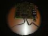
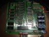
Please see attachments for some photos.
I hink you are right about the manufactures bespoke 3 pin fitting it looks very much like an XLR with different wiring set up.
I knew what each of the red, yellow and black wires were doing then I am sure I may be able to have it rewired even if it were to use 2 seperate 6 and 12v output power supplies.
Certainly an interesting one!!
 

Attachments

  • 7_t.jpg
    7_t.jpg
    2 KB · Views: 290
  • 8_t.jpg
    8_t.jpg
    3.2 KB · Views: 284
  • 6_t.jpg
    6_t.jpg
    2.3 KB · Views: 320
  • 3_t.jpg
    3_t.jpg
    2.8 KB · Views: 286

davelectronic

Dec 13, 2010
1,087
Joined
Dec 13, 2010
Messages
1,087
Chess psu

Hi again Mart.
I dont know how confidant you are with building a unit, my way would be about the 30VA chassis mount transformer, at single or twin secondary windings, 12 volts straight out for that rail, and a power resistor to drop for the 6 volts, a ventilated case fuse the mains input, and fuse the secondary before the power resistor for the output at say 5 amps fuse, chassis mount holders for both fuse holders, and ground the case for safety if its metal.

My guess, but not definite, is red 6 volts and yellow 12 volts, black ground, if you can open it up and follow the pin notations to components you will see what pin is what voltage.

A quick way is a pair of AC adapters in a dual line socket, not my preference, and more expensive, but quicker, wired to a suitable plug. Dave. :)
 

Mart

Sep 16, 2011
13
Joined
Sep 16, 2011
Messages
13
Hello Dave. I have tried to attach some clearer images of the machine etc.

You can see the red yellow and black wires on the top right connecting to the P1 connection on the M Board, as I said before the red wire comes straight from the centre pin of the male connector and the yellow and black go to a switch with a 24v ceramic capacitor soldered between the 2 wires then out of the switch to the P1 connector.
If the black was ground would it be going to the switch with the capcitor between it and the yellow wire?

I have just sourced a power supply in the USA that is for these machines
http://www.hosfelt.com/contents/en-us/d472.html


It has a 120v vac input but I will get over this with a step transformer 240ac to 120 vac.
The problem is that this company will only export if you spend a minimum of $50 + $5 handling charge then the shipping, import duty and vat etc!!!

Not to worry I do have an electronics friend but he is very ill at the moment, when he gets a bit better i'll ask him to have a look.
Many thanks.
Mart.
 

Attachments

  • 7_f.jpg
    7_f.jpg
    123.3 KB · Views: 291
  • 8_f.jpg
    8_f.jpg
    149.1 KB · Views: 368
  • 6_f.jpg
    6_f.jpg
    157.4 KB · Views: 297
Last edited:

Resqueline

Jul 31, 2009
2,848
Joined
Jul 31, 2009
Messages
2,848
The circuit could either be making +8V & +16V, or +8V & -8V. The +8V surely then being regulated to +5V. I've circled the area of interest, but check upper right corner.
Perhaps you can follow the copper tracks (&/or do some measurements) and see where the pins of P1 leads to, and what the capacitors & diodes are connected to.
 

Attachments

  • 8_f.jpg
    8_f.jpg
    85.4 KB · Views: 374

davelectronic

Dec 13, 2010
1,087
Joined
Dec 13, 2010
Messages
1,087
Chess psu

Hi again Mart.
I can clearly see the bridge rectifier, capacitor bank, and discharge load resistors, and a voltage regulator in the bottom of Resqueline's out line in the picture, i could knock up a psu in no time at all but to talk you through building from scratch is a tall order.

I wish you all the best luck with it, to me the circuit board looks of good quality, certainly a contender worthy of a power supply. Dave. :)
 

(*steve*)

¡sǝpodᴉʇuɐ ǝɥʇ ɹɐǝɥd
Moderator
Jan 21, 2010
25,510
Joined
Jan 21, 2010
Messages
25,510
I have a colleague who has built a PSU for one of these.

He used a 12V centre tapped transformer.

If you want more details I can get them from him and post them.
 

Mart

Sep 16, 2011
13
Joined
Sep 16, 2011
Messages
13
I have a colleague who has built a PSU for one of these.

He used a 12V centre tapped transformer.

If you want more details I can get them from him and post them.

Hello Steve. The centre tap would be for ground/earth?
Any details would be a tremedous gesture and would be much appreciated and I would gladly reimburse any costs.

The thing is with things like this the challange to make it work becomes as big as actually having it work again!!

I have a couple of avenues to check out and will get back to you.
Thanks.
 

Mart

Sep 16, 2011
13
Joined
Sep 16, 2011
Messages
13
Hi again Mart.
I can clearly see the bridge rectifier, capacitor bank, and discharge load resistors, and a voltage regulator in the bottom of Resqueline's out line in the picture, i could knock up a psu in no time at all but to talk you through building from scratch is a tall order.

I wish you all the best luck with it, to me the circuit board looks of good quality, certainly a contender worthy of a power supply. Dave. :)

Hello Dave.
Yes what a quality board!!
For once a manufacturer did not cut costs, these machines where built to last.
Thanks again.
 

(*steve*)

¡sǝpodᴉʇuɐ ǝɥʇ ɹɐǝɥd
Moderator
Jan 21, 2010
25,510
Joined
Jan 21, 2010
Messages
25,510
Hello Steve. The centre tap would be for ground/earth?
Any details would be a tremedous gesture and would be much appreciated and I would gladly reimburse any costs.

I believe my colleague is planning to join and post the details.

He mentioned that there is some data on the web, but that it is well hidden, and he feels that documenting his solution is probably not a bad thing.

He related how he created a replacement plug from molex pins and carved wood.

I have (somewhere) the artwork for his PCB design, so I'll try to find that...
 

Mart

Sep 16, 2011
13
Joined
Sep 16, 2011
Messages
13
I believe my colleague is planning to join and post the details.

He mentioned that there is some data on the web, but that it is well hidden, and he feels that documenting his solution is probably not a bad thing.

He related how he created a replacement plug from molex pins and carved wood.

I have (somewhere) the artwork for his PCB design, so I'll try to find that...

Carefull Steve you know what happened to Tron with that CPU who started out as a chess engine!!
 

(*steve*)

¡sǝpodᴉʇuɐ ǝɥʇ ɹɐǝɥd
Moderator
Jan 21, 2010
25,510
Joined
Jan 21, 2010
Messages
25,510
My colleague (who may appear shortly) told me that the Computer Museum has this manual available for download. That too may be useful.
 

nfman

Sep 20, 2011
7
Joined
Sep 20, 2011
Messages
7
I am that colleague :)

As Steve said, I built a power supply for one of these a year or so ago. The forums at chesscomputer.org (although the URLs say boardnation.com) have some very useful information about the Grandmaster / Phantom power supply here and here.

Those two threads seem to be difficult to search for, so I won't be surprised if you've not come across them before.

Depending on how much time I find myself with this evening, I'll document some or all of my power supply for a later post.
 

nfman

Sep 20, 2011
7
Joined
Sep 20, 2011
Messages
7
Warning: I am a computer programmer who knows how to wield a soldering iron without causing too much damage (most of the time) - not an electronics "anything". I don't really know if this is a good solution, but it's worked ok so far.

I'd like to document this properly (what follows is a bit confusing) but here is some basic information on what I did.

After discovering the links I posted earlier, I tracked down a 12v (6+6) centre tapped transformer and wired it all up, using the chesscomputer.org forum post about molex pins to attach the transformer to the chess robot itself.

At this point, it was a nasty mess of live wires, and the transformer wasn't really up for the load and got rather warm after about 10 mins. I'd confirmed it worked, but not an ideal solution to let the kids loose on!

In the final power supply, used this 30VA 6+6 transformer which seems to function well. Being on 240v in this part of the world, I bridged the primaries, and took 0, 6 and 12v off the secondaries. With 6v being from centre tap, I arbitrarily picked 0 and 12v from the two outer pins.

Here is the PCB layout I used (hastily updated with 0..12v labels):

chess2electronicspoint.png

Hopefully this will be enough for you to be going on with until I can unearth the camera and write it up properly :)
 

Mart

Sep 16, 2011
13
Joined
Sep 16, 2011
Messages
13
Amazing contribution form you guys.
Plenty to work on there.
Many thanks.
 

(*steve*)

¡sǝpodᴉʇuɐ ǝɥʇ ɹɐǝɥd
Moderator
Jan 21, 2010
25,510
Joined
Jan 21, 2010
Messages
25,510
Wait until he describes the hand carved power plug :)
 
Top