Use LED to denote current flow in AC circuit

DontLetTheSmokeOut

Aug 18, 2012
17
Joined
Aug 18, 2012
Messages
17
All,

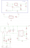
I'm using this 555 based polarity switching circuit as my base:
https://www.electronicspoint.com/555-timer-reverse-polarity-circuit-t250411.html

My supply is 30V DC so I'm using a DPDT relay to switch the legs. I'd like to put LEDs in the actual legs to show that everything is truly working.

I've attached what I'm trying and would like constructive :) comments.


D1, D2 - reverse breakdown voltage is 4V
D3, D4 - reverse breakdown voltage is 3.6V

I put the zeners in there thinking that they would "protect" the other leds. Is this necessary?

thanks,
dave
 

Attachments

  • Capture.JPG
    Capture.JPG
    16.4 KB · Views: 288

DontLetTheSmokeOut

Aug 18, 2012
17
Joined
Aug 18, 2012
Messages
17
Ok after thinking about this (and googling), I think it makes more sense to just put a 1N4148 in series with the LEDs. The spice sim looks good as well.

5278d1345586982-use-led-denote-current-flow-ac-circuit-capture1.jpg


dave
 

Attachments

  • Capture1.JPG
    Capture1.JPG
    11 KB · Views: 385
Last edited by a moderator:

davenn

Moderator
Sep 5, 2009
14,470
Joined
Sep 5, 2009
Messages
14,470
your images are too small, I cant see any detail see if you can make them a little bigger .... say ~648 x 480

the LED's are going to need resistors in series for current limiting else they are going to die in a bright flash

But until you give a readable diagram I cant help any further

Dave
 

duke37

Jan 9, 2011
5,364
Joined
Jan 9, 2011
Messages
5,364
I think you could get away with two leds connected in inverse parallel, then putting a 300 ohm in series. The forward voltage for the led must be less than the reverse breakdown voltage of the other led.
 

DontLetTheSmokeOut

Aug 18, 2012
17
Joined
Aug 18, 2012
Messages
17
The problem with this circuit is that all the current (40mA) will go through each LED and that may be too much for the diode. I don't think the current limiting resistor will do anything because the LM317 is going to do everything it can to drive 40mA, well unless I make the resistor so big that it can't do that because there is 30v supply limit.

Maybe I just go with LEDs that can support a 40mA forward bias current and go with this one.

dave

Ok after thinking about this (and googling), I think it makes more sense to just put a 1N4148 in series with the LEDs. The spice sim looks good as well.


dave
 

Attachments

  • Capture2.JPG
    Capture2.JPG
    28.4 KB · Views: 183

DontLetTheSmokeOut

Aug 18, 2012
17
Joined
Aug 18, 2012
Messages
17
As you can see I'm not afraid to talk to myself.

I had to dust off some 20 year old memories and remembered Kirchhoff is your friend. After looking at it that way, I figured I could easily fix this. If I have 40mA flowing through the current, and want to limit the forward bias current in the LED, I took the LED forward bias voltage at a safe current level, used that voltage and current to determine the value of the resistor to put in parallel to the LED. This appears to work.

Here are my "hopefully" final results.

dave
 

Attachments

  • Capture3.JPG
    Capture3.JPG
    42.1 KB · Views: 244
  • Capture4.JPG
    Capture4.JPG
    99.3 KB · Views: 158

davenn

Moderator
Sep 5, 2009
14,470
Joined
Sep 5, 2009
Messages
14,470
As you can see I'm not afraid to talk to myself.

I had to dust off some 20 year old memories and remembered Kirchhoff is your friend. After looking at it that way, I figured I could easily fix this. If I have 40mA flowing through the current, and want to limit the forward bias current in the LED, I took the LED forward bias voltage at a safe current level, used that voltage and current to determine the value of the resistor to put in parallel to the LED. This appears to work.

Here are my "hopefully" final results.

dave

you are still attaching just thumbnails images. show us a larger image so we can see what you are doing

cheers
Dave
 

DontLetTheSmokeOut

Aug 18, 2012
17
Joined
Aug 18, 2012
Messages
17
That is odd, when I click on the attachment it opens up across my entire screen. The images attached are about 1100x770 pixels.

I uploaded them to photobucket, maybe this will work better.

Capture3.jpg

Capture4.jpg


dave

you are still attaching just thumbnails images. show us a larger image so we can see what you are doing

cheers
Dave
 
Last edited:

duke37

Jan 9, 2011
5,364
Joined
Jan 9, 2011
Messages
5,364
I talk to myself also - very enlightening.

The images work OK for me except the simulation which is too dark.
 

Harald Kapp

Moderator
Moderator
Nov 17, 2011
14,271
Joined
Nov 17, 2011
Messages
14,271
I have no trouble reading the images, they open up large and clear.

As to the circuit:
Why do you use a sine source with 40mV amplitude? 40mV are insufficient to light up the LEDs and from the use of a DPDT relay I'd assume that the waveform is more of the pulse type.
Also why do you have the load current flow through the indicator circuit?

Have a look at this circuit:
attachment.php

- The voltage source is replaced by a rectangular pulsed source with an amplitude of 30 V - nearer to your description.
- The load (Rload) is directly connected to the voltage source.
- The indicator circuit is in parallel to the load. Thus you can adjust the LED current by changing R1 independent from the load current.
- The LEDs do not need protection diodes. The reverse breakdown voltaeg of an LED is on the order of 5 V. This is more than the forward voltage of the LEDs. Thus each LEd works as the protection diode for the other LED since the voltage across the LEDs cann never be higher than the mximum LED forward voltage.
 

Attachments

  • Led.gif
    Led.gif
    16.2 KB · Views: 553

DontLetTheSmokeOut

Aug 18, 2012
17
Joined
Aug 18, 2012
Messages
17
This circuit is just to model the alternating current seen in the legs of the dpdt relay. So I used an alternating current source to model that. Its not a voltage source.

Here is the entire circuit.

dave

I have no trouble reading the images, they open up large and clear.

As to the circuit:
Why do you use a sine source with 40mV amplitude? 40mV are insufficient to light up the LEDs and from the use of a DPDT relay I'd assume that the waveform is more of the pulse type.
Also why do you have the load current flow through the indicator circuit?

Have a look at this circuit:
attachment.php

- The voltage source is replaced by a rectangular pulsed source with an amplitude of 30 V - nearer to your description.
- The load (Rload) is directly connected to the voltage source.
- The indicator circuit is in parallel to the load. Thus you can adjust the LED current by changing R1 independent from the load current.
- The LEDs do not need protection diodes. The reverse breakdown voltaeg of an LED is on the order of 5 V. This is more than the forward voltage of the LEDs. Thus each LEd works as the protection diode for the other LED since the voltage across the LEDs cann never be higher than the mximum LED forward voltage.
 

Attachments

  • Version2.png
    Version2.png
    16.5 KB · Views: 189

Harald Kapp

Moderator
Moderator
Nov 17, 2011
14,271
Joined
Nov 17, 2011
Messages
14,271
So I used an alternating current source to model that. Its not a voltage source
Of course. my fault. But do you really need to see the current or do you just require an indicator for the polarity of the switched voltage? In the latter case you can put my circuit (without the voltage source) between pins 4 and 9 of the relay.
 
Last edited:

DontLetTheSmokeOut

Aug 18, 2012
17
Joined
Aug 18, 2012
Messages
17
I like that solution. Removes some complexity and reduces components. It routes up easier for my board solution as well.

thanks,
dave
 
Top