Few Questions about Sound on Light

(*steve*)

¡sǝpodᴉʇuɐ ǝɥʇ ɹɐǝɥd
Moderator
Jan 21, 2010
25,510
Joined
Jan 21, 2010
Messages
25,510
It was combined with another thread by Harald Kapp, one of the Super moderators/moderators......

You're right. And maybe we should consider moving it somewhere more appropriate.
 
Last edited:

Electro132

Feb 12, 2013
261
Joined
Feb 12, 2013
Messages
261
Steve,

I've built it but there's bad news and good news. Bad news is the IR LED is not functioning when i place a square wave into the circuit place where the amplifier goes. Even when i place an amplifier the IR LED still doesn't turn purple when i use my mobile camera on it.

Good news - i got the power supply and 33 ohm resistor working so i know that the voltage works at least, just not the rest of the circuit. Have you got any ideas why its doing that?
 

(*steve*)

¡sǝpodᴉʇuɐ ǝɥʇ ɹɐǝɥd
Moderator
Jan 21, 2010
25,510
Joined
Jan 21, 2010
Messages
25,510
The LED should glow (invisibly) as soon as you connect the power.

use a multimeter to measure the voltage across the resistor and also across the LED.

Tell us what they are.
 

Electro132

Feb 12, 2013
261
Joined
Feb 12, 2013
Messages
261
The LED should glow (invisibly) as soon as you connect the power.

use a multimeter to measure the voltage across the resistor and also across the LED.

Tell us what they are.


The voltage on the resistor (33 ohm) is 2.974 v but no voltage is running across to the Zener and IR LED. I've checked the zener and the IR LED and they work ok. i've soldered everything correctly so i'm not sure what's wrong. I'll upload some pics soon. I'll try again today.
 

(*steve*)

¡sǝpodᴉʇuɐ ǝɥʇ ɹɐǝɥd
Moderator
Jan 21, 2010
25,510
Joined
Jan 21, 2010
Messages
25,510
What zener?
 

davenn

Moderator
Sep 5, 2009
14,470
Joined
Sep 5, 2009
Messages
14,470
Zener diode (protective diode) that protects the IR LED from too much current.

what zener ?? there isnt a zener diode in the circuit, well not one marked as such anyway and if you have one in there then you shouldnt !! :)

Dave
 

Electro132

Feb 12, 2013
261
Joined
Feb 12, 2013
Messages
261
what zener ?? there isnt a zener diode in the circuit, well not one marked as such anyway and if you have one in there then you shouldnt !! :)

Dave

How come? Doesn't a zener diode help protect the IR LED from receiving too much current? That was my initial understanding why there was a protective diode there in the first place since it provides a voltage threshold which doesn't allow the current to overflow the threshold.
 

(*steve*)

¡sǝpodᴉʇuɐ ǝɥʇ ɹɐǝɥd
Moderator
Jan 21, 2010
25,510
Joined
Jan 21, 2010
Messages
25,510
If you're talking about the ordinary diode in parallel with the LED, then that's just a normal diode.
 

Electro132

Feb 12, 2013
261
Joined
Feb 12, 2013
Messages
261
YAY! i got it to work. Thanks Steve. I'm going to try it out with some apps. Btw, how do you make the IR LED go farther in terms of distance so i can cover more ground?
 

Electro132

Feb 12, 2013
261
Joined
Feb 12, 2013
Messages
261
I re-soldered the components onto a new baord. Seems like the old one had broken tracks or something as it wasn't generating any current onto the diode and IR LED.
 

(*steve*)

¡sǝpodᴉʇuɐ ǝɥʇ ɹɐǝɥd
Moderator
Jan 21, 2010
25,510
Joined
Jan 21, 2010
Messages
25,510
YAY! i got it to work. Thanks Steve. I'm going to try it out with some apps. Btw, how do you make the IR LED go farther in terms of distance so i can cover more ground?

OK, firstly, were you able to modulate the light intensity and prove it by using a phototransistor etc., to receive the signal and convert it back to sound?

There are several ways of increasing the range. You may have to try all of them.

The first and simplest is to increase the average current to the LED (possibly using multiple LEDs) and ensure your depth of modulation is high. This will be a lot easier if you drive the LED (s) from a constant current source where the current is set by an incoming voltage (your signal).

However, that's only going to go so far.

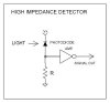
Next you'll need to make a far better receiver, and one which is sensitive to variations in incoming IR sensitivity (rather than the absolute amount it sees). This will allow your receiver to work with higher ambient IR illumination.

To get even more range you need to move to a digital signal where the LED is only tuned on for brief periods (typically at a very high current). This is pretty much how IR remote controls work. The encoded data can be at a higher data rate than your audio signal, does not rely on analog input signals, and can use compression and redundancy to allow errors to be corrected.

As you move from one level of complexity to another, the complexity of your circuit will also rapidly increase.
 

(*steve*)

¡sǝpodᴉʇuɐ ǝɥʇ ɹɐǝɥd
Moderator
Jan 21, 2010
25,510
Joined
Jan 21, 2010
Messages
25,510
True.

Great for point to point stuff. Less so for "broadcasting" or where one end of the link moves.
 

Electro132

Feb 12, 2013
261
Joined
Feb 12, 2013
Messages
261
OK, firstly, were you able to modulate the light intensity and prove it by using a phototransistor etc., to receive the signal and convert it back to sound?

No, not yet. I tried to send through the IR LED a Square wave at 108 hz but nothing was happening. So i tried it at 108000 hz (which is like 108 khz right?) and still got nothing. So i'm wondering whether i need a transducer or something to convert the signal and then send it through before i go ahead with any other sounds?.


The first and simplest is to increase the average current to the LED (possibly using multiple LEDs) and ensure your depth of modulation is high. This will be a lot easier if you drive the LED (s) from a constant current source where the current is set by an incoming voltage (your signal).

However, that's only going to go so far.

How do i make my depth of modulation high? You mean make the wave peak and trough wider?


To get even more range you need to move to a digital signal where the LED is only tuned on for brief periods (typically at a very high current). This is pretty much how IR remote controls work. The encoded data can be at a higher data rate than your audio signal, does not rely on analog input signals, and can use compression and redundancy to allow errors to be corrected.
 

(*steve*)

¡sǝpodᴉʇuɐ ǝɥʇ ɹɐǝɥd
Moderator
Jan 21, 2010
25,510
Joined
Jan 21, 2010
Messages
25,510
No, not yet. I tried to send through the IR LED a Square wave at 108 hz but nothing was happening. So i tried it at 108000 hz (which is like 108 khz right?)

Well, 108Hz is a very low frequency and 108kHz is very high.

Why not start with 1kHz?

What are you doing to receive the signal and amplify it?
 

Electro132

Feb 12, 2013
261
Joined
Feb 12, 2013
Messages
261
Well, 108Hz is a very low frequency and 108kHz is very high.

Why not start with 1kHz?

What are you doing to receive the signal and amplify it?

That's not such a bad idea. I'll do that. Also, do you think having 2 transistors in place one after the other increases the voltage output from a 3 v source? i've heard of darlington pair or something like that to amp the voltage output.

On the receiving end, i know that having a phototransistor will pick up the light signal but i just want to make sure that it's the right circuit. I've attached something.
 

Attachments

  • high recvr.jpg
    high recvr.jpg
    14.9 KB · Views: 86

(*steve*)

¡sǝpodᴉʇuɐ ǝɥʇ ɹɐǝɥd
Moderator
Jan 21, 2010
25,510
Joined
Jan 21, 2010
Messages
25,510
I would recommend you use a phototransistor instead of a photodiode (they're easier to work with).

Also, the symbol you've used for your amplifier is an inverter. I hope this isn't what you mean.

If you have an amplifier of some sort with a microphone input, a phototransistor and resistor connected up the same way you have the photodiode and resistor will work, but you need to AC couple the output to the amplifier (the same way that you AC couple the output of another amplifier to your LED -- with a capacitor in series).

If using a phototransistor, the most common wiring will have the collector connected to +ve and the emitter connected to the resistor (and this is also where the signal will appear)
 

Electro132

Feb 12, 2013
261
Joined
Feb 12, 2013
Messages
261
I would recommend you use a phototransistor instead of a photodiode (they're easier to work with).

Ok Cool.

Just also with the range thing, i was thinking maybe using a thyristor in place after amping the voltage current up with some transistors so i could get more range out of the LED. I know transistors have two versions npn and pnp but i'm still a little confused about the 2 of them. I know one has the arrow coming into the transistor (pnp) and the other has the arrow coming out (npn) but not sure which is best to use to amp the voltage current. What are pnp's used for anyway? converters?
 

(*steve*)

¡sǝpodᴉʇuɐ ǝɥʇ ɹɐǝɥd
Moderator
Jan 21, 2010
25,510
Joined
Jan 21, 2010
Messages
25,510
PNP and NPN transistors are kinda like left hand drive and right hand drive vehicles.

They do pretty much exactly the same thing, but everything is reversed in one compared with the other.

I can't see any reason to use a thyristor.
 
Top