Problem with IC LM324

anv273

Jun 26, 2014
8
Joined
Jun 26, 2014
Messages
8
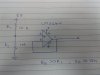
I tried to connect one of the op-amps in LM324 as buffer amplifier. (unity gain)

But the output is not matching with the input.. I tried for different input voltages.. but there is always a voltage drop of 0.95 volts..

Could somebody please explain the reason for this? If it is the problem with the IC, could anybody suggest me a better alternative for this? ( single supply Quad operational amplifier)
 

Harald Kapp

Moderator
Moderator
Nov 17, 2011
14,273
Joined
Nov 17, 2011
Messages
14,273
The reason for this is surely a mistake in your setup. The LM324 is a workhorse. Show us a schematic diagram of your circuit. Did you observe the limits for the LM324 according to the datasheet (operating voltages, input voltage range, output voltage range etc.)?
 

anv273

Jun 26, 2014
8
Joined
Jun 26, 2014
Messages
8
Vcc+ =5V
Vcc- = ground
Input voltage Vin+ is given from a voltage divider circuit. R1 = 10K ; R2= 1M
Vin- is connected to output.
 

Harald Kapp

Moderator
Moderator
Nov 17, 2011
14,273
Joined
Nov 17, 2011
Messages
14,273
A schematic would be so much more helpful. Does your divider generate 0.05V or 4.95V? Without knowing how R1 and R2 are connected to the power supply, both are possible solutions.

At 0.05V the amplifier should work since the input common mode voltage includes 0V.
At 4.95V the amplifier can't work. Its input common mode voltage is limited to V+-1.5V (see datasheet). At 5V this translates to max. 3.5V!

Note also that the output voltage is limited to somwhere around V(+)-1V at moderate output currents. which wil limit the achievable voltage range, too.

Try the circuit with R1=R2 making the input voltage 2.5V. Then the output should follow the input and you can eliminate any possibly existing errors in the setup of the circuit. Then vary the resistor ration (tip: use a potentiometer) to find the working limits of your circuit.

If you nedd the circuit to operate close to 0V and 5V, Google "rail-to-rail" opamp. Insect carefully the datasheet of the component of your choice. Some opamps are called rail-to-rail but only for the inputs or outputs, not both.
 

Harald Kapp

Moderator
Moderator
Nov 17, 2011
14,273
Joined
Nov 17, 2011
Messages
14,273
What do you mean by rail to rail op-amp?
Please stay within your thread, do not open a new thread for related posts. I merged the two into this one.

From the Wikipedia: "Some modern devices have "rail-to-rail output" capability, meaning that the output can range from within a few millivolts of the positive supply voltage to within a few millivolts of the negative supply voltage." I'd like to add that the same naming convention holds for the inputs of an opamp, too.
 

anv273

Jun 26, 2014
8
Joined
Jun 26, 2014
Messages
8
Iam sorry....... But I still did not get it completely...

The buffer has an output that exactly mirrors the input (assuming it's within range of the voltage rails)

What does the above statement mean?
 

(*steve*)

¡sǝpodᴉʇuɐ ǝɥʇ ɹɐǝɥd
Moderator
Jan 21, 2010
25,510
Joined
Jan 21, 2010
Messages
25,510
The buffer

An op-amp set up as a unity gain voltage follower

has an output that exactly mirrors the input

has a voltage at the output which is exactly the same as the voltage at the input

(assuming it's within range of the voltage rails)

as long as the input voltage is in a sensible range (the output can't go beyond -- or even completely to -- the supply rails)
 

anv273

Jun 26, 2014
8
Joined
Jun 26, 2014
Messages
8
A schematic would be so much more helpful. Does your divider generate 0.05V or 4.95V? Without knowing how R1 and R2 are connected to the power supply, both are possible solutions.

At 0.05V the amplifier should work since the input common mode voltage includes 0V.
At 4.95V the amplifier can't work. Its input common mode voltage is limited to V+-1.5V (see datasheet). At 5V this translates to max. 3.5V!

Note also that the output voltage is limited to somwhere around V(+)-1V at moderate output currents. which wil limit the achievable voltage range, too.

Try the circuit with R1=R2 making the input voltage 2.5V. Then the output should follow the input and you can eliminate any possibly existing errors in the setup of the circuit. Then vary the resistor ration (tip: use a potentiometer) to find the working limits of your circuit.

If you nedd the circuit to operate close to 0V and 5V, Google "rail-to-rail" opamp. Insect carefully the datasheet of the component of your choice. Some opamps are called rail-to-rail but only for the inputs or outputs, not both.


This is my circuit. My aim is to operate the circuit close to 0 V and 5V. I dont know much about rail to rail op-amps. LM324 is a common opamp used as buffer. That is why I chose it.
 

Attachments

  • 20140707_120308.jpg
    20140707_120308.jpg
    86.7 KB · Views: 419

anv273

Jun 26, 2014
8
Joined
Jun 26, 2014
Messages
8
My actual objective is this:

I need to replace the 1M resistor by a resisitive pressure sensor. The voltage divider converts the resistance change to usable voltage. The sensor input has to be buffered before sending it to ADC of PIC16F887. The output of buffer should be in the range of 0-5 V before being fed to ADC.
 

OLIVE2222

Oct 2, 2011
690
Joined
Oct 2, 2011
Messages
690
Your schematic is the 4.95V case identified by Harald who can't work with a LM324. As rail-to-rail op amp you can use a cheap MCP6001 from Microchip. You must carefully chose your resistor in the divider to match the pressure range with the ADC reference.
Also note that your 5V that supply the divider is (probably) not a voltage reference, mean can be up to +/-5 % tolerance !

Olivier
 
Last edited:

(*steve*)

¡sǝpodᴉʇuɐ ǝɥʇ ɹɐǝɥd
Moderator
Jan 21, 2010
25,510
Joined
Jan 21, 2010
Messages
25,510
That circuit will give you an output between ground and the supply rail, BUT it won't actually get to ground or the positive supply rail.

Because of that, if the input goes beyond where the output can go, the output won't be able to follow the input.

If you arrange that the input varies from (say) 1v to 3v, then you should be ok.

Similarly, if the LM324 was operated from supply rails of -2v and 7v, you could get a complete 0 to 5v output swing.

If you take a look at the datasheet for the LM424 you'll see it specifies the input and output swing in terms of the supply rails. In your case this is vital information.
 
Top