DSP/Amp Problem (Reversed Polarity)

Riley1

Feb 3, 2016
47
Joined
Feb 3, 2016
Messages
47
If I hit the reset switch I have 3.27 in both places until it drops out.
 

Gryd3

Jun 25, 2014
4,098
Joined
Jun 25, 2014
Messages
4,098
What puzzles me the most is the voltage called 3P3V_ON.
I can't see how this is "generated".
3P3V_ON is generated on the TDA3681J Linear Reg. (U4)
There is a block diagram of this chip on Page 82. Pin4 (Named 'Reg4') looks to be the source.
Page 98 has the wiring diagram of what else this output is connected to.


Have any measurements been done on U23? "C8051F347"
Pin 17 on here is the 'Power Enable Pin' . It's a microcontroller which appears to control the vReg.
It's output gets inverted through U10... so keep in mind that the Power_Enable out of U23 will be the OPPOSITE to what you measure on Pins 9, 10, and 11 on U4 (The TDA3681J regulator)
 
Last edited:

dorke

Jun 20, 2015
2,342
Joined
Jun 20, 2015
Messages
2,342
3P3V_ON is generated on the TDA3681J Linear Reg. (U4)
There is a block diagram of this chip on Page 82. Pin4 (Named 'Reg4') looks to be the source.
Page 98 has the wiring diagram of what else this output is connected to.


Have any measurements been done on U23? "C8051F347"
Pin 17 on here is the 'Power Enable Pin' . It's a microcontroller which appears to control the vReg.
It's output gets inverted through U10... so keep in mind that the Power_Enable out of U23 will be the OPPOSITE to what you measure on Pins 9, 10, and 11 on U4 (The TDA3681J regulator)

No,that is not that.
There are 2 different 3.3V
1. 3P3V this is generated by U4 on pin 4 it feeds most 3.3v of the circuit
2. 3P3V_ON a different voltage,
it only feeds the μC(U23) and U10,U26.kind of a STBY voltage.
(with 5V_ON)

I think I found it (from the note on the sch),
it is generated by the μC U23 (pin 6) from the 5V_ON voltage(pin 7).
Like so:

3P3V_ON.jpg
 

Gryd3

Jun 25, 2014
4,098
Joined
Jun 25, 2014
Messages
4,098
No,that is not that.
There are 2 different 3.3V
1. 3P3V this is generated by U4 on pin 4 it feeds most 3.3v of the circuit
2. 3P3V_ON a different voltage,
it only feeds the μC(U23) and U10,U26.kind of a STBY voltage.
(with 5V_ON)

I think I found it (from the note on the sch),
it is generated by the μC U23 (pin 6) from the 5V_ON voltage(pin 7).
Like so:

View attachment 25002
http://www.mouser.com/ds/2/368/C8051F34x-46984.pdf
Missed that :s
found the datasheet for it though. Page 21 I'm sure is of interest.
 

Riley1

Feb 3, 2016
47
Joined
Feb 3, 2016
Messages
47
Do I need to have power on pin 5 (remote in) while making these checks?

Thanks,
Rick
 
Last edited:

dorke

Jun 20, 2015
2,342
Joined
Jun 20, 2015
Messages
2,342
Do I need to have power on pin 5 (remote in) while making these checks?

Thanks,
Rick

Good question.
Don't know,worth trying to see if it makes any difference.

Is there a J5(USB connection) on the board?
Anything connected to it?
 

Riley1

Feb 3, 2016
47
Joined
Feb 3, 2016
Messages
47
I'm getting close to getting out the hammer and fixing this thing.:D

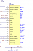
TP4 I have 3.5V. Here'e the weird thing. At the terminals I jumpered terminal 1&3 to get 12V on the remote in and flipped the power on and had 12V at the terminals. I noticed the power light stayed on, although it blinked after 30 seconds and then stayed on. I took some readings on U4 and here's what I got. A few minutes later I check the voltage at the terminals and I have 9.3 fluctuating down to 7.5 with the jumper connected or not and the power lights stays on although a slight flicker (low voltage?).

VC.png
 

dorke

Jun 20, 2015
2,342
Joined
Jun 20, 2015
Messages
2,342
When you say " voltage at the terminals" are you talking about the input voltage to the unit i.e VCAR?
If so,I guess you are still working with the P.S.
Does that P.S have a current limit "set knob"?
If it does crank it up to it's maximum.

Can you measure the current that the unit is drawing from the P.S,
connect a DMM in series ,at DC AMP (10A or higher)to measure that.
 

Riley1

Feb 3, 2016
47
Joined
Feb 3, 2016
Messages
47
When you say " voltage at the terminals" are you talking about the input voltage to the unit i.e VCAR?
If so,I guess you are still working with the P.S.

Yes and yes.I haven't had the voltage issue except when I put power to the remote in terminal.

Does that P.S have a current limit "set knob"?
If it does crank it up to it's maximum.
Not sure but I'll check tomorrow.

Can you measure the current that the unit is drawing from the P.S,
connect a DMM in series ,at DC AMP (10A or higher)to measure that.

Will do.

Thanks,
Rick
 

Gryd3

Jun 25, 2014
4,098
Joined
Jun 25, 2014
Messages
4,098
Yes and yes.I haven't had the voltage issue except when I put power to the remote in terminal.
You might be attempting to draw too much current with the jumper in place.
How much current can your supply provide again? (A spare car battery would help here... at least for short tests, but because it has almost no current limit, if you accidentally short something, bad things can happen)
 

Riley1

Feb 3, 2016
47
Joined
Feb 3, 2016
Messages
47
I was currently using a 3A. I now have a 20A. I'll check again with the new power supply.
 

Riley1

Feb 3, 2016
47
Joined
Feb 3, 2016
Messages
47
Voltage drops to 7V with the new power supply as soon as I jumper the remote in, pull the jumper and it's back to 12V. I'll check current draw next.
 

Gryd3

Jun 25, 2014
4,098
Joined
Jun 25, 2014
Messages
4,098
Voltage drops to 7V with the new power supply as soon as I jumper the remote in, pull the jumper and it's back to 12V. I'll check current draw next.
Hrm..
Just confirming. Pins 3 and 17, do they remain at 12V as the other pin fluctuates?
 

Riley1

Feb 3, 2016
47
Joined
Feb 3, 2016
Messages
47
Hrm..
Just confirming. Pins 3 and 17, do they remain at 12V as the other pin fluctuates?
No, they fluctuate.

Current draw is 4.1 amps. I also noticed when checking voltage (remote jumper in) if I let it run for a few minutes every once in a while the voltage briefly will run up to 11.5V and then drop back to 6.87. I noticed this as the rpm's on the power supply fan would drop. Pull the jumper and it sticks at 12V.

Thanks,
Rick
 

Riley1

Feb 3, 2016
47
Joined
Feb 3, 2016
Messages
47
Using a second meter shouldn't I be able to get a voltage reading while measuring current?

Thanks,
Rick
 

Gryd3

Jun 25, 2014
4,098
Joined
Jun 25, 2014
Messages
4,098
Using a second meter shouldn't I be able to get a voltage reading while measuring current?

Thanks,
Rick
Rick, if the voltage at those two points fluctuate, can you please measure the following points?
1 - Terminal 1 (Battery Input)
2 - Any point 'After' the 25A Fuse. (On the 12V side of D2 or D34)
3 - Any point 'After' the L20 Inductor. (+ side of C95 or C38)
Please do this while keeping the negative meter probe on Terminal 2 (Term Ground)

VCar 'Should' be the same voltage as what your power supply is putting out, and that goes directly to pins 3 and 17 on that chip you measured... if you are getting less than 12V, then one of two things is happening:
- There is a component in-line that is a high-resistance that causes a voltage drop when current is pulled.
- The power supply cannot cope with the current draw and it dips when current is pulled.

If the voltage dips at step 1, then it's the power supply. If 1 is fine, then the other two points should let us know.
(Are you using a new fuse? It's possible for a component to fail, and still measure properly with a simple resistance reading... When the component attempts to carry load, the fault becomes much more clear.

And yes.. you can put Meter 1, in-line with the power supply and amplifier to read current, while you use meter two to poke around for voltage. Be careful though, as meter 1 may be required to pass numerous amps to your device... Make sure it's rated high enough!
 
Top