Converting 3 phase machine to single phase

Arbid

Feb 4, 2017
8
Joined
Feb 4, 2017
Messages
8
Hello,

Currently experiencing issue understanding this I have attached the images.

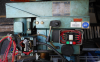
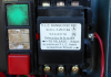
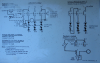
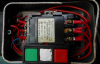
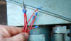
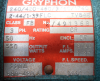
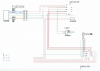
It has 2 conductors and it shows in the diagram to remove the link between 2 and 3 and join A to L2 but doesn't say from which conductor I should remove this links from. Also which 2 cables would be the live and neutral from the 6 cables?

Would greatly appreciate it if you could help.

Many thanks
 

Attachments

  • Screen Shot 2017-02-04 at 14.59.30.png
    Screen Shot 2017-02-04 at 14.59.30.png
    922.5 KB · Views: 74
  • Screen Shot 2017-02-04 at 14.58.57.png
    Screen Shot 2017-02-04 at 14.58.57.png
    677.2 KB · Views: 93
  • Screen Shot 2017-02-04 at 14.58.11.png
    Screen Shot 2017-02-04 at 14.58.11.png
    713.5 KB · Views: 79
  • Screen Shot 2017-02-04 at 14.57.56.png
    Screen Shot 2017-02-04 at 14.57.56.png
    707.5 KB · Views: 82
  • Screen Shot 2017-02-04 at 14.57.41.png
    Screen Shot 2017-02-04 at 14.57.41.png
    800.6 KB · Views: 83

Minder

Apr 24, 2015
3,561
Joined
Apr 24, 2015
Messages
3,561
Does the machine have 3ph devices on it such as 3 ph motors? As in the first screen shot.
If so there is more than just a little re-wiring,
If it is the case, you would need a VFD for them, It could be that the DWG just shows the difference in wiring between two different machine versions, not necessarily indicating it can be switched easily.
M.
 

Arbid

Feb 4, 2017
8
Joined
Feb 4, 2017
Messages
8
Does the machine have 3ph devices on it such as 3 ph motors? As in the first screen shot.
If so there is more than just a little re-wiring,
If it is the case, you would need a VFD for them, It could be that the DWG just shows the difference in wiring between two different machine versions, not necessarily indicating it can be switched easily.
M.

Hello Minder,

Thanks for your reply.

Yes the machine does have a 3 phase motor attached. As you suggested for the VFD, how would I go about connecting this?

Many thanks
 

Minder

Apr 24, 2015
3,561
Joined
Apr 24, 2015
Messages
3,561
You would need to find a space in the enclosure or set up a new one to contain the VFD, If feeding from 240v 1phase service the motor is required to either be the same voltage rating or settable to 240v 3ph.
A decent low priced one is Hitachi, I would stay away from the cheaper Chinese Huanyang etc.
The manuals that are included with any VFD informs how to set up the wiring for it.
Also it entails setting the necessary parameters to match the motor.
There is another way called a RPC, rotary phase convertor, but by the time you have finished it would cost around the same as a VFD, and not as good a solution.
M.
 

Fish4Fun

So long, and Thanks for all the Fish!
Aug 27, 2013
481
Joined
Aug 27, 2013
Messages
481
@Minder the OP's pictures would seem to indicate the motors are 3-phase synchronous induction motors designed for 50hz-60hz grid operation .... while a typical VFD is certainly capable of 50-60hz output, they are NOT typically designed for 1) Running Multiple Motors 2) Allowing the output legs to be "Switched" or "Opened", Since this machine almost certainly does both ("E-Stop", "Forward/Neutral/Reverse", "Brake") it is likely NOT a candidate for a typical VFD.

@Arbid .... I can't tell from the pictures exactly what type of machine this is, perhaps a milling machine? In any case the **best** option is to have 3-phase service installed; however, in many cases this simply isn't financially practical. (Obviously installing a properly sized 3-phase alternator/generator is functionally equivalent, and might be cheaper a bit cheaper) The second best solution is a rotary phase converter ..... these are essentially a 110v/220v single phase motor and a 3-phase alternator/generator built on a common shaft .... RFC's up to ~10HP are fairly easy to source and frequently a fraction of the cost of having 3-phase service installed. The cheapest option is a "Static Phase Converter" .... Static Phase Converters perform well-enough in some situations, but have some very real limitations .... for instance "Breaking" is frequently achieved by "Removing One Leg", this typically doesn't work very well with Static Phase Converters .... In order to "Reverse" direction the motor HAS TO remain in "Neutral" until it comes to a FULL STOP or the Static Phase Converter and/or motor can be destroyed. A static phase converter has to be properly matched to the motor and you must have a separate static phase converter for each motor **NO EXCEPTIONS**. As if the static phase converters didn't already have a lot negatives, your motors will only run @ ~60% of their name-plate power when operated in this manner. So, while a Rotary Phase Converter is likely going to seem like a lot of money, it is almost certainly the cheapest way to get your machine 100% functional.

Here's a link to a 5hp model..... https://www.wolfautomation.com/inde...UMZgBUjCrAKfYB44FSH5MQOe28kVsk3RL0xoCg9nw_wcB

If you need more than 5HP, be advised they are considerably more expensive both up-front and to operate simply because Single-Phase motors > 5HP (continuous duty) are large, relatively inefficient beasts.

Good Luck!

Fish
 

Minder

Apr 24, 2015
3,561
Joined
Apr 24, 2015
Messages
3,561
@Minder the OP's pictures would seem to indicate the motors are 3-phase synchronous induction motors designed for 50hz-60hz grid operation .... while a typical VFD is certainly capable of 50-60hz output, they are NOT typically designed for 1) Running Multiple Motors 2) Allowing the output legs to be "Switched" or "Opened", Since this machine almost certainly does both ("E-Stop", "Forward/Neutral/Reverse", "Brake") it is likely NOT a candidate for a typical VFD.

I would be interested how you came to this conclusion?
Having had a career of CNC retro-fitting for quite a few decades now, I don't see how it cannot be a consideration without further information on the machine.
Also the myth of 'motor output must not be switched' is just that, a myth, it depends on the application and if done correctly, i.e. ensuring the VFD is At-Zero-Speed, it can be done, I have controlled multiple conveyors this way.
Just about all CNC machines control the spindle variable controller with E-stop, FWD/REV, braking, and most VFD's have this feature.
IMO you are spreading misinformation in the absence of further data.
To the OP, check out CNCzone also,
M.
 
Last edited:

Minder

Apr 24, 2015
3,561
Joined
Apr 24, 2015
Messages
3,561
Arbid: Can you show the info on the motor plate, the rpm and voltage will show the nature of the motor.
Is there only one motor on this machine? As it looks like only one contactor.
M.
 

Arbid

Feb 4, 2017
8
Joined
Feb 4, 2017
Messages
8
Many thanks for your replies guys.

What I will do is take some more pictures tomorrow and upload them as the machine is located at another location.
 

Bluejets

Oct 5, 2014
7,374
Joined
Oct 5, 2014
Messages
7,374
By the look of what is in the first photo it appears to be a milling machine.
I doubt there would be any other motor than the main drive, except of course if there is a coolant pump.
Other consideration would be the lighting transformer which may have to be changed.

I'd tend to get a local electrician to rearrange just the motor wiring as shown in the single phase arrangement on a test basis and watch motor current to see what happens. Nothing untoward is going to happen in a few moments testing.

I'd suggest you do not do this yourself as you will get into problems.
 

Minder

Apr 24, 2015
3,561
Joined
Apr 24, 2015
Messages
3,561
3ph in UK is 415v , single ph 240v.
Not sure how a 3ph 415?v motor will run on that?
Unless there is a delta connection for it.
M.
 

Bluejets

Oct 5, 2014
7,374
Joined
Oct 5, 2014
Messages
7,374
Agree....without knowing what is inside the motor terminal box then just a guess.

It may be a star connection which some small hp tend to be which would give a final 2 parellel, in series with the remaining winding when connected as shown for single phase.

This may give a sort of shaded pole effect for rotation but just guessing wildly out loud now.
 

Arbid

Feb 4, 2017
8
Joined
Feb 4, 2017
Messages
8
Hi Guys,

Yes, this is a milling machine with a single motor and as you suggested Bluejets there is a coolant pump.

I have just attached another picture of what I found on the machine.

Also I have attached another image, were I have chased the wiring and that's how it is connected at the moment.
 

Attachments

  • Screen Shot 2017-02-05 at 14.25.57.png
    Screen Shot 2017-02-05 at 14.25.57.png
    671.2 KB · Views: 99
  • Screen Shot 2017-02-05 at 14.27.02.png
    Screen Shot 2017-02-05 at 14.27.02.png
    373.2 KB · Views: 187

Minder

Apr 24, 2015
3,561
Joined
Apr 24, 2015
Messages
3,561
As I predicted it is a star-delta 4 pole induction motor, delta for 220v and star for 380-420.
I don't see how they would have connected this motor for 1 phase.
I suspect that may have been a generic drawing for hooking the contactor up when either type of motor is fitted.
Also if the motor previously ran on 420, and you change to 220, you may have to change any overloads in order to stop nuisance tripping.
Although if you fit a VFD, the O/L's can be by-passed.
I would think the viable economic option for 1phase is to use a VFD for the main motor and possibly change out the pump motor or the whole pump to 1ph.
M.
 
Last edited:

Minder

Apr 24, 2015
3,561
Joined
Apr 24, 2015
Messages
3,561
Just ensure the model is Sensorless-Vector not just V/Hz.
M.
 

Arbid

Feb 4, 2017
8
Joined
Feb 4, 2017
Messages
8
If I get the VFD which hp would be sufficient for this motor?

I have 7 wires as shown in the 1st image exc earth but from the videos I have seen I only require 3 cables from the machine to connect the VFD. So how would I got about connecting this?

Also, I assume if I get a VFD only the motor will work and not the pump if I am just connecting 3 of these cables from the 7?

Many thanks
 

Minder

Apr 24, 2015
3,561
Joined
Apr 24, 2015
Messages
3,561
Check the motor terminal block, it most likely has two rows of 3 terminals, and some brass straps.
If connected star they will be 3 horizontally across the top, for delta (240) they would be all three vertical 3ph in on each strap.
The motor appears to be <1hp so the current rating shown would be what you need to size the VFD.
If a 3ph pump motor, then you would need to change out the motor or the pump, it is not economical to fit a VFD for this.
M.
Electric-Motor-Star-and-Delta-wiring-and-link-Connections-206x300.jpg
 
Last edited:
Top