Capacitor Protection Boards- How do they work?

AprilSteel

Feb 2, 2017
111
Joined
Feb 2, 2017
Messages
111
No that was not my intention I just wondered if an LED can be added to the single round board to show when it is conducting. My guess was to put it in series with one of the conducting resistors maybe.
 

(*steve*)

¡sǝpodᴉʇuɐ ǝɥʇ ɹɐǝɥd
Moderator
Jan 21, 2010
25,510
Joined
Jan 21, 2010
Messages
25,510
Doubtful, and I'd like to see how it's done on the other board.

There's no point reinventing the wheel.
 

(*steve*)

¡sǝpodᴉʇuɐ ǝɥʇ ɹɐǝɥd
Moderator
Jan 21, 2010
25,510
Joined
Jan 21, 2010
Messages
25,510
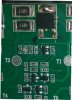
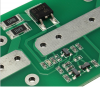
You'll need to take a better photo. We need to be able to read the values on the resistors and the markings on the other devices.

However, it's already clear that this circuit is substantially more complex than the last one. Is not simply a case of a LED being stuck somewhere.
 

hevans1944

Hop - AC8NS
Jun 21, 2012
4,979
Joined
Jun 21, 2012
Messages
4,979
Designations aside, the circuit seems very similar to the one I discussed here.

The obvious differences are:
  1. Yours uses a BJT as the pass element
  2. Yours has load resistors to both limit current and to help dissipate heat.
  3. Mine has a pulldown resistor for the gate of the mosfet that is not required in yours due to (1)
  4. The values of the voltage divider resistors are different due to a different "breakdown" voltage.
I sure am glad you posted that link, Steve. It led me to your adventures in laser ablation of circuit board "resist" using paint sprayed onto bare copper-clad boards. And it sure does look like your constant voltage load circuit, re-purposed to "protect" supercaps from excessive terminal voltage while charging them.:cool:

Not to hijack this thread, but now I know why you went all ga-ga at Mendelson's when you spotted all those bare copper laminates at dirt-cheap prices.:D
 

Bhargav Makodia

Sep 10, 2017
3
Joined
Sep 10, 2017
Messages
3
You'll need to take a better photo. We need to be able to read the values on the resistors and the markings on the other devices.

However, it's already clear that this circuit is substantially more complex than the last one. Is not simply a case of a LED being stuck somewhere.
Find below reply with more clear image Reply#27
 

(*steve*)

¡sǝpodᴉʇuɐ ǝɥʇ ɹɐǝɥd
Moderator
Jan 21, 2010
25,510
Joined
Jan 21, 2010
Messages
25,510
If possible kindly convert it into circuit diagram.

You've seen the method, how far along the path can you get yourself?

I'm interested in how this circuit works, but I don't have time to do the reverse engineering again.
 

(*steve*)

¡sǝpodᴉʇuɐ ǝɥʇ ɹɐǝɥd
Moderator
Jan 21, 2010
25,510
Joined
Jan 21, 2010
Messages
25,510
Obviously @Bhargav Makodia isn't going to put in the effort, but since I am somewhat curious, here is my first attempt:
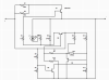
upload_2017-12-28_9-43-29.png

That's based on the positions on the board and the polarity determined by the only marked semiconductor (the 2SD1804).

All the unmarked semiconductors are assumed to be transistors and I've had an incomplete guess as to whether they'd be more sensibly NPN or PNP (note I have Q4 as marked in this diagram incorrect). The unpopulated resistors are shown using a different resistor symbol.
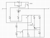
upload_2017-12-28_9-49-22.png

A bit of minor cleanup, correction of Q3 (was Q4), and the identification of the TL431 (which had to be hiding in there!).

Q3 is a bit of a mystery. I think the purpose is to short out R11 while the voltage across the capacitor is very low. Presumably this keeps the TL431 firmly OFF at low voltages. The datasheet doesn't suggest there is any low voltage weirdness, but hey, it's only a guess right now.
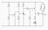
upload_2017-12-28_10-28-48.png

And with a bit more manipulation, I have what might be close to the circuit. I will admit, Q3 is bothering me a bit...

The answer to the indicator is fairly simple. And that could be added to the other circuit.
 

(*steve*)

¡sǝpodᴉʇuɐ ǝɥʇ ɹɐǝɥd
Moderator
Jan 21, 2010
25,510
Joined
Jan 21, 2010
Messages
25,510
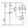
As stated above, the original circuit:

upload_2017-12-28_12-58-54.png

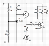
Could probably be changed to:

upload_2017-12-28_12-59-35.png

it's interesting that the R2 is 100k as opposed to 180k in the other circuit.

edit: looking closely, R2 is 180k in the original circuit. It was a bit hard to read from the photo, but with a closer look... (and it has been corrected)
 
Last edited:

AprilSteel

Feb 2, 2017
111
Joined
Feb 2, 2017
Messages
111
You have been busy Steve while I was away. Ill have to try out your circuit now so give me a few days . I've moved on to getting LiFePo4 batteries charged properly but thats another thread.
 
Top