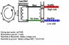
You can have a voltage that is the sum of a DC component and an AC component (
see e.g. here).
With an ordinary multimeter:
When the meter is in DC setting, it will average the AC component if the frequency is more than a very few Hz. The average of an AC component is 0 V, so the meter displays the DC component only.
When the meter is in AC setting, typically a capacitor blocks any DC component. The remaining AC component is rectified, measured and displayed.
Og course, there exist advanced meters that perform so called RMS metering. These meters will calculate the
RMS of the combined voltage and will in the case of a mixed waveform thus display a different value than an ordinary multimeter.
You can use a series capacitor to block the DC component, then use an ordinary amplifier to boost the remaining AC to the desired level.