Testing Procedure For this Component

H2814D

Nov 4, 2017
258
Joined
Nov 4, 2017
Messages
258
Hi all. I have removed for testing a TS2576, a step down voltage switching regulator. It was on a 12vdc to 12/8/6vdc power supply board. The power supply is to an RV Stereo/CD/DVD system for which I cannot find a schematic diagram (Quest QX3202DVD). The pins, from left to right, are supposed to be this: 1. Input 2. SW Output 3. Ground 4. Feedback 5. Enable. I am wondering just exactly how to tell if this component is working correctly. I have connected a dc power supply to pin 1, and the voltage out from pin 2 matches whatever the voltage input on pin 1 is. So far, I have only used voltages from 5-8 vdc though, since I was not sure how much this item will handle. Can someone provide me with the testing procedure for this, and try to explain as if you are talking to an idiot please. :)
 

Attachments

  • TS2576.PNG
    TS2576.PNG
    301.3 KB · Views: 23

(*steve*)

¡sǝpodᴉʇuɐ ǝɥʇ ɹɐǝɥd
Moderator
Jan 21, 2010
25,510
Joined
Jan 21, 2010
Messages
25,510
If you look at the datasheet you will find some samples circuits. The best test would be to place the TS2576 in such a circuit and ensure it does what it should.
 

hevans1944

Hop - AC8NS
Jun 21, 2012
4,968
Joined
Jun 21, 2012
Messages
4,968
This device cannot be used as a stand-alone step-down switching voltage regulator without providing additional components. At a minimum, an inductor, a fly-wheel schottky diode, an input capacitor and an output capacitor are required. If not the fixed output voltage variation, then a feedback resistor network to set the output voltage is also required.

As @(*steve*) said: read the datasheet and apply the required components for testing.
 

kellys_eye

Jun 25, 2010
6,512
Joined
Jun 25, 2010
Messages
6,512
With it actually 'in position' - what did you measure as the input and what did you measure as the output? What evidence did you have to justify its removal for out-of-circuit testing?
 

H2814D

Nov 4, 2017
258
Joined
Nov 4, 2017
Messages
258
Since I don't have a schematic, and this thing runs a dvd/cd player in addition to an am/fm stereo, I thought maybe this component is what sends the current to the dvd/cd drive when the radio/dvd switch is put on dvd. Something has to do that. :)

I never measured the voltage while in position, because it is kind of compacted in place near other components and enclosed in a heat sink. I suppose I can solder some wires to it and check it that way, while in position, and while activating the radio/dvd switch. I just thought it would have a test procedure like most other components.

Thanks for your help so far.
 

(*steve*)

¡sǝpodᴉʇuɐ ǝɥʇ ɹɐǝɥd
Moderator
Jan 21, 2010
25,510
Joined
Jan 21, 2010
Messages
25,510
This is the heart of a switch mode regulator.

If the power supply is the correct voltage then it's working.
 

kellys_eye

Jun 25, 2010
6,512
Joined
Jun 25, 2010
Messages
6,512
That device could be supplying the am/fm section too.....

What does the unit do/not do? If the DVD isn't working, in what way isn't it working? No discussion spinning?

That could just be the drive motor or, if fitted, a drive belt????
 

hevans1944

Hop - AC8NS
Jun 21, 2012
4,968
Joined
Jun 21, 2012
Messages
4,968
I just thought it would have a test procedure like most other components.
The manufacturer no doubt has a test procedure, but the best "test" is to connect it as suggested in the application notes, or re-connect it to the original circuit, "fire 'er up" and perform the proverbial "smoke test." If it gets hot and emits smoke under normal operating conditions, then you can be sure there is a problem somewhere you need to investigate and correct. If it just gets warm and produces the correct output voltage under load, that's a pretty good sign the device is operating as intended and whatever problem or problems you are experiencing are located elsewhere. OTOH, if it remains at room temperature and produces no output voltage, there may be something wrong with the component. Only then would you remove it and replace it with a "known good" component. However, before doing that you need to make sure the problem does not lie in the support components: capacitors, inductor, schottky diode, resistor feedback network (if present), and the raw DC supply input.

Willy-nilly pulling components for "testing" is not an efficient troubleshooting procedure. In the absence of a schematic, you need to make intelligent guesses (based on experience) as to proper operating voltages, probe around the circuits with your multimeter in voltmeter mode, and do the same thing with an oscilloscope to trace signal paths. If possible, locate a schematic for a similar piece of equipment and compare circuits by doing a bit of "reverse engineering" on the unit you are attempting to repair. The effort required to do all of this is why most electronics is replaced instead of repaired today.

If you really want to develop a test procedure for this component, look at and understand the block diagram below, copied from the datasheet. Then set up external circuits that exercise and test the functions "inside the box" using the manufacturer's specifications found in the datasheet. This is really not of any value unless you plan on testing and evaluating hundreds (or thousands) of these components.

upload_2018-9-11_10-18-12.png

Good luck with your troubleshooting!
 

H2814D

Nov 4, 2017
258
Joined
Nov 4, 2017
Messages
258
Thanks again for your suggestions. Can you just tell me this about the above Block Diagram? I want to see if I have this right.

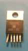
The "Block" as depicted is the component (TS2576). The numbers contained in the boxes are the component pins. The supplied DC current going into pin 1 will eventually get to the load through pin 2, but only if pin 5 is grounded, which apparently "enables" the supplied current to flow through the component to pin 2, and then to the load. And pin 2 should always be the same voltage as what is being supplied to pin 1, because this particular component is not one that changes voltage. Because of this, I am guessing pin 5 must be manually activated (enabled) in some way, and because it is "enabled" by grounding it, that enabling device must be connected to a ground somewhere. So maybe a switch of some type, connected to a ground, may be that enabling device? Pin 3 is the grounded portion of this component. That's easy enough. So I see pin 4 is taking the output of pin 2 and running it back through the component for various checks (over voltage, thermal maximums, etc.). I am guessing that pin 4 is more of a safety measure for this component. Is my assessment of this component fairly accurate?

If the above is correct, I should be able to solder 4 wires to the device while in circuit, using the grounded heat sink as pin 3. If I ground pin 5, pin 2 should then allow the current to flow and I should get the same voltage from pin 2 as I have going in to pin 1. If pin 5 is grounded, I should also get the same voltage from pin 4. If pin 5 is not grounded, I should not get any voltage from pin 2 or pin 4.

What concerns me is this: While out of circuit, this component should not supply current to pin 2 unless pin 5 is grounded...and it does. I attached 5 vdc to pin 1 and grounded pin 3. The voltmeter read the same voltage on pin 2 as supplied on pin 1, and pin 5 was not attached to anything.

Ok...I'm ready to get hammered. You guys are good at that. Haaa.

Sorry, guys, but my background is not in electronics. This is just for fun and a challenge. I have, however, learned a lot just from reading your replies to other questions.
 

H2814D

Nov 4, 2017
258
Joined
Nov 4, 2017
Messages
258
That device could be supplying the am/fm section too.....

What does the unit do/not do? If the DVD isn't working, in what way isn't it working? No discussion spinning?

That could just be the drive motor or, if fitted, a drive belt????
The AM/FM is working correctly. The drive is not spinning now and where I used to get "Loading/No Disk,Track Info" on the LCD, I am not seeing that anymore.
 

(*steve*)

¡sǝpodᴉʇuɐ ǝɥʇ ɹɐǝɥd
Moderator
Jan 21, 2010
25,510
Joined
Jan 21, 2010
Messages
25,510
And pin 2 should always be the same voltage as what is being supplied to pin 1

No. Pin 2 is either connected to pin 1 (when the transistor is on) or disconnected from it (when the transistor is off).

The transistor turns on and off many times per second.

In most cases, when the transistor turns off the voltage at pin 2 drops to a diode drop below ground.

To understand how this device works you also need to understand how energy is stored in an inductor. You can't really look at the device in isolation from the essential components that are connected to it.

Edit: on/off - what's the difference really?
 
Last edited:

davenn

Moderator
Sep 5, 2009
14,470
Joined
Sep 5, 2009
Messages
14,470
If the above is correct, I should be able to solder 4 wires to the device while in circuit, using the grounded heat sink as pin 3. If I ground pin 5, pin 2 should then allow the current to flow and I should get the same voltage from pin 2 as I have going in to pin 1. If pin 5 is grounded, I should also get the same voltage from pin 4. If pin 5 is not grounded, I should not get any voltage from pin 2 or pin 4.

no, it isn't correct
if you got the same voltage out of pin 2 as what went into pin 1, then the device isn't doing any voltage regulating, aye?


I am guessing that pin 4 is more of a safety measure for this component

No, it isn't, did you notice where the line from Pin4 goes to ?
It monitors the output voltage and provides a feedback signal to the error amplifier and oscillator circuits inside the IC to keep a stable/constant output from the regulator

AGAIN ….
If you haven't read the datasheet as @hevans1944 linked to way up the page …...
https://www.rapidonline.com/pdf/156...9_1536718896_fed4a5af8130f7e3518c33d5c2c83d32

Do so ! … Then, if there is anything in the datasheet you don't understand, that's cool,
just come back here and ask specific questions


Dave
 
Top