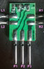
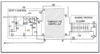
We will be interested in the small sensor board in your #23 photo of your post #7.
Have the board disconnected from the plug that it normally goes into, and then go into your meters OHMS mode and test for the SMD resistors values as being
22,000 ohms
1500 ohms
62000 ohms
Realize that we will then have to take a little foil slice out between R14 and R15, for correcting of shunted readings, and then solder bridge the gap later.
Also . . . whilst you gots ye olde ohmmeter warmed up and running good . . . . test for resistance of all possible resistance connections of the
PCBs central 2 Top and 2 Bottom tabs:
TL to TR
TL to BL
TL to BR
TR to BL
TR to BR
BL to BR
And then use DIODE test mode of the DVM for checking out the junctions of the PNP transistor Q1.
Collector is the sole tab at the top near the Q1 symbolization
Base is the bottom left tab
Emitter is bottom right tab
Expect in the range of ~500------ 800 millivolts for good junctions.
73's de Edd