Hi All,
I can't believe my eyes when I found this thread.
I also have a VZUG hob Model GK36TIPSF with exactly the same problem - doesn't power on. Up till now it has been an outstanding unit.
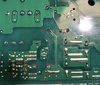
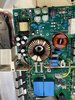
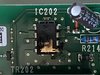
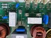
I removed it to investigate and same IC202 blown it's top off, and resistor R214 looks sunburnt.
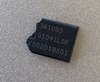
BUT! I found the top of the IC. It reads "Infeneon" ICE3A1065. G1041L0P. K002018X01.
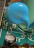
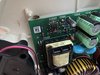
AND I found the cockroach or a friend of his.
I have ordered 10 of these chips
https://au.rs-online.com/web/p/pwm-current-mode-controllers/1107480/
Data sheet
https://docs.rs-online.com/ccca/0900766b814d6c8b.pdf
Prudence90 I'm happy to share some spares with you.
Would people think this was a good path to go down? Anyone able to help me identify the resistor R214?
Thanks a truckload!
I can't believe my eyes when I found this thread.
I also have a VZUG hob Model GK36TIPSF with exactly the same problem - doesn't power on. Up till now it has been an outstanding unit.
I removed it to investigate and same IC202 blown it's top off, and resistor R214 looks sunburnt.
BUT! I found the top of the IC. It reads "Infeneon" ICE3A1065. G1041L0P. K002018X01.
AND I found the cockroach or a friend of his.
I have ordered 10 of these chips
https://au.rs-online.com/web/p/pwm-current-mode-controllers/1107480/
Data sheet
https://docs.rs-online.com/ccca/0900766b814d6c8b.pdf
Prudence90 I'm happy to share some spares with you.
Would people think this was a good path to go down? Anyone able to help me identify the resistor R214?
Thanks a truckload!

")