Transistor AND gate question

Bluejets

Oct 5, 2014
7,374
Joined
Oct 5, 2014
Messages
7,374
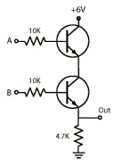
Output-HIGH-1.gif
Page 22 in spot the mistakes........
http://www.talkingelectronics.com/projects/SpotMistakes/SpotMistakesP22.html

Show what you have done......
Are you using LEDs as output..??
Do you have low's and Hi's connected or just left one input floating...??
 
Last edited:

Tristan369

Oct 29, 2020
32
Joined
Oct 29, 2020
Messages
32
All I was doing was I had two transistors. The first transistor had the emitter going into the second's base. That second transistor has an LED on its emitter and 5V on its collector. No matter how I arrange the values of resistors, simply plugging 5V into the first transistor's base activates the second transistor, which makes an AND gate impossible. You can't send current into B's base without it flowing through its emitter.
 

Harald Kapp

Moderator
Moderator
Nov 17, 2011
14,289
Joined
Nov 17, 2011
Messages
14,289
All I was doing was I had two transistors. The first transistor had the emitter going into the second's base.
That is not the circuit shown in the diagram. Show us a diagram of the circuit you really made.
simply plugging 5V into the first transistor's base activates the second transistor
Of course, that's matches perfectly your verbal description.

Talking about a "first" and a "second" transistor and then of inputs "A" and "B" doesn't give us a clue as to which is which.
 

Tristan369

Oct 29, 2020
32
Joined
Oct 29, 2020
Messages
32
All I am asking you is how is an AND gate possible if setting a transistor's base high sets its emitter high too?

I guess now that I think about it, if it didn't do that, you could just use a single transistor as an AND gate, with the base and collector being A and B.
 

Harald Kapp

Moderator
Moderator
Nov 17, 2011
14,289
Joined
Nov 17, 2011
Messages
14,289
That's all shown and explained on the website you linked in your 1st post. If something there is not clear to you, please go into more detail and explain where you fail. AND supply a schematic of your circuit. It is hard to guess from a verbal description what a circuit looks like.

For example:
setting a transistor's base high sets its emitter high too?
- What kind of transistor are you using? PNP or NPN?
- How is the emitter connected to the rest of the circuit? To GND, to Vcc, with or without a resistor?

There are so many possibilities. Leaving us in the dark about your circuit won't get you any useful answers.
 

Tristan369

Oct 29, 2020
32
Joined
Oct 29, 2020
Messages
32
No it doesn't, in fact it uses that picture as a solution for an AND gate. I have tried that exact circuit and it doesn't work. Again, even when just "B" is high, so is the output.
 

Harald Kapp

Moderator
Moderator
Nov 17, 2011
14,289
Joined
Nov 17, 2011
Messages
14,289
in fact it uses that picture as a solution for an AND gate.
O.K., fine. But that's not what you described in post #3. See why pictures are important?

have tried that exact circuit and it doesn't work.
"it doesn't work" is not a helpful description - at least not helpful to us. To help you analyze the issue, please provide:
  1. expected operation (e.g. expected voltages)
  2. measured operation
From there on we can move forward analyzing the discrepancies which, as explained below) in this case may be due to different expected behavior, not incorrect operation of the circuit.

Again, even when just "B" is high, so is the output.
That will depend on where you put your threshold for a signal being High or Low. With the values given in the image (post #2):
  • With "A" being High and "B" being Low or with both "A" and "B" being LOW the output voltage will be 0 V, therefore Low (assuming no load on the output).
  • With "B" being High and "A" being Low, the output voltage will be ~ 1.6 V (again no load). In a 6 V logic system this voltage may or may not be considered Low. As it is below 1/2 Vcc (1/2 × 6 V = 3 V), one could define it as Low. This would work with many CMOS logic gates. In classic TTL logic this would not necessarily work as 1.6 V is within the "forbidden" range.
  • With both "A" and "B" being High, output voltage will be ~5.3 V, a clear High.
If the Low voltage in the second case above is too high for your purposes, reduce the 4.7 kΩ resistor to e.g. 470 Ω. This will give you ~0.25 V, a clear Low.
 

Tristan369

Oct 29, 2020
32
Joined
Oct 29, 2020
Messages
32
Oh I see. Well my problem is that even 0.25v is enough to turn on another 2n2222 transistor. Do I just need a huge resistor going to the base of every transistor? I'm trying to build a simple adder circuit.
 

ratstar

Aug 20, 2018
485
Joined
Aug 20, 2018
Messages
485
All I was doing was I had two transistors. The first transistor had the emitter going into the second's base.

you want the emitter going to the collector not the base. the base is where the variables go.

good luck with ur adder. :)
 

Tristan369

Oct 29, 2020
32
Joined
Oct 29, 2020
Messages
32
After remaking it on my breadboard it works I think I had the resistor values mixed up 2k looks almost exactly like 10k color codes, I just tried it with B having a 2k resistor and it creates my problem. It's literally the difference between a slightly brighter red band lol How did you find out that it turns on at .5v? That is incredibly useful information I couldn't find anything about it on one of its datasheets https://www.onsemi.com/pub/Collateral/P2N2222A-D.PDF
 

TCSC47

Mar 7, 2016
148
Joined
Mar 7, 2016
Messages
148
This is a classic AND gate circuit found in text books. What is not shown is how the "0" and "1" inputs are produced. If you assume that "0" is simply to not apply a +6V to either of the inputs, then the circuit is not likely to work. The inputs have to be taken down to 0V for "0" and up to 6V for "1".
Is that what you are doing?
 
Top