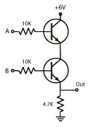
in fact it uses that picture as a solution for an AND gate.
O.K., fine. But that's not what you described in post #3. See why pictures are important?
have tried that exact circuit and it doesn't work.
"it doesn't work" is not a helpful description - at least not helpful to us. To help you analyze the issue, please provide:
- expected operation (e.g. expected voltages)
- measured operation
From there on we can move forward analyzing the discrepancies which, as explained below) in this case may be due to different expected behavior, not incorrect operation of the circuit.
Again, even when just "B" is high, so is the output.
That will depend on where you put your threshold for a signal being High or Low. With the values given in the image (post #2):
- With "A" being High and "B" being Low or with both "A" and "B" being LOW the output voltage will be 0 V, therefore Low (assuming no load on the output).
- With "B" being High and "A" being Low, the output voltage will be ~ 1.6 V (again no load). In a 6 V logic system this voltage may or may not be considered Low. As it is below 1/2 Vcc (1/2 × 6 V = 3 V), one could define it as Low. This would work with many CMOS logic gates. In classic TTL logic this would not necessarily work as 1.6 V is within the "forbidden" range.
- With both "A" and "B" being High, output voltage will be ~5.3 V, a clear High.
If the Low voltage in the second case above is too high for your purposes, reduce the 4.7 kΩ resistor to e.g. 470 Ω. This will give you ~0.25 V, a clear Low.