I would have posted this initially.What is missing is a schematic showing the power supply voltage and the forward voltages and wiring of the "multiplicity" of LEDs,.
Really? Then I strongly suggest you be VERY careful while you work on it!
Because: If the designer of your "setup" was really willing to waste 15V across what's nothing but a heat-producing ballast resistor, then the total supply voltage across resistor plus series LED chain can be expected to total well above 100V, creating an obviously dangerous shock hazard.
Otherwise they're a very poor designer to create such an inefficient circuit, and the "setup" can be expected to be dangerous just from being a lousy design.
Because: If the designer of your "setup" was really willing to waste 15V across what's nothing but a heat-producing ballast resistor,
Then please help me change the voltage to something more appropriate and simple fitting a ballast resistor.
Sorry - working with IR. I also measured voltage = 1.25 empirically with multimeter.Guess what? Red LEDs are not 1.23V. Instead they are 1.8V to 2.1V when at about 15mA.
Look out for those moving goal posts.....![]()
If you mean my edits, I apologize. I mis-read the way Mr. 101 labeled his LED voltages.
What a magnificent alpha predator. I had the chance to meet one in Georgia when it dove in and lifted a rabbit off of the road in front of me.View attachment 55778 View attachment 55781
Why not connect all your LEDs in a single series string and power them all from a single resistor, thus drawing only half the current? Sketch attached.
By the way, the photo is of a beautiful red shouldered hawk that kindly paid me a visit one day outside my office window -- not an owl.
What a magnificent alpha predator. I had the chance to meet one in Georgia when it dove in and lifted a rabbit off of the road in front of me.
Series would be easier but I need the parallel for setup purposes.
The resistor in that case will be in series with the LED/LEDs so their voltage drop must be subtracted first.
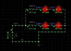
i.e. if you have 2 red LEDs in series with your resistor, you must first subtract 2 x 1.7v (or there abouts) first.
Remainder is the voltage that will appear across the resistor.
If 12v supply, then 12 -(2 x 1.7v = 3.4v) = 8.6v.
You then need to calculate the resistor at 8.6v divided by whatever current through the LEDs (say 20mA)
So resistor is 8.6/0.20 = 430R.
As that is not a standard size, then go to 470R, you won't be able to see the difference.
Then the watage would be 8.6 (v) x 0.02 (A) = 0.172W .....so 1/4w resistor.
Maybe a picture will help. What is the voltage across the resistor? Hint: You'll never know until you measure it with an actual voltmeter.
View attachment 55771
Maybe a picture will help. What is the voltage across the resistor? Hint: You'll never know until you measure it with an actual voltmeter.
View attachment 55771

View attachment 55786
Ok so I've reduced the voltage to 5v and the current is being drawn is
33.6 ma. The LEDs are getting sufficient current. What is the max current I should look for given a 5V supply? I came across one PS that had 5V with 2000ma.
It was a question of voltage and efficiency. Not current.No, sorry max current of the power supply for this circuit. As you pointed out my 15V 300-400ma PS was seriously flawed. So what instead?
Thanks