I’ve tested the paths of diodes, capacitors,Etc. And all check out good. solonoid tests good as well. I know I’m missing something and really needing some help. Thank you
Sorry for the blurred pics. These should be betterThe image of the schematic looks to say Q808 - it's very blurred on my screen and could be different! It's the transistor with the collector connected to the coil.
yes, I actually tested with a 9v battery and it worked. any suggestions?When you say the solenoid tests good, do you mean you have applied power and seen it work? I am asking because I have seen solenoid windings heat up and expand, jamming the plunger, but they still check ok with a meter.
It's a wonder you managed to get any movement out of it with 9v.yes, I actually tested with a 9v battery and it worked. any suggestions?
I’ll check Q802 today. Also attached another pic of schematic. They all should be much clearer. Sorry for the piecemeal. And again, really appreciate all of your help and patience with this novice.It's a wonder you managed to get any movement out of it with 9v.
Supply rail appears to be 27v so is that ok...??
You say you shorted Q808 (which doen't appear to exist) but what about Q802, which, even though rather blurry, I think is the switch for the solenoid.
I too, have had solenoids jam as ivak245 says.
Might be a good move to post clear photos and some further detail from the power supply further down the schematics page.
All rather vague on the answers.
Just checked Q802 and shorted, plunger worked! I did replace Q802 with a spare board I bought on ebay but still nothing unless I short it.I’ll check Q802 today. Also attached another pic of schematic. They all should be much clearer. Sorry for the piecemeal. And again, really appreciate all of your help and patience with this novice.
I don’t blame you for rolling your eyes, lol. I did look at it before I attached. I’ll try again. I’ll also check your suggestions as well. Fingers crossed on the pic. Huh!Cannot make out any detail on the new photo as it is too small to make out any detail.
Did you look at it when you posted it...???
Q802 is ....(from what I can make out on previous photo #1 )... driven by Q803 via a couple of (what looks like) either R1 or F1 inputs.
Actually that is written in the text beside the schematic.
Any signal there...??

Did you look at it when you posted it...???![]()
I Flipped itDOHHHH!!! ......now it's upside down.......(Goto #12)
First if all, I’m really sorry for the pics if not coming out clear. My phone takes great pics but not sure why when attaching they are not clear. I have gone back and checked F1 and R1 for voltage which there is. Unfortunately I’m a real novice when it comes to this but always want to learn. At this point not sure if I need to throw in the towel, and don’t want to test all you wonderful peeps who have been helping me, your patience. I’ll take any direction if you still want to help me, but understand if not. You guys helped me on my 1st tape deck, but I’m running out of brain cells! Lol. Have a great dayDOHHHH!!! ......now it's upside down.......(Goto #12)
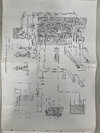
Solenoid appears to get it's signal (whatever form that takes) from the control unit via either F1 or R1 (assume forward or reverse)
There is a "zero rewind" switch sw10 which would, I imagine, disable/enable that feature.
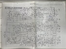
You may possibly need access to some form of a scope if the signals are pwm or similar pulses to determine if signals are indeed being generated.
Perhaps trace your main supplies and see if they are good. (12v ) you have determined you have 27v by the previous test #11.
Still can't read the damned schematic!