I thought you would never ask!
Where in the world are you located?
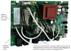
You see saying you have "240VAC coming in" and trying to describe your dilemma means nothing to me. Could you possibly take some photos where you're taking your measurements. They're just too many variables. We must narrow them down.
Others here may know off the top of their heads but I frown upon speculation and I do wish to help you.
In the US,1P(single phase) 240V Power is provided to homes and small buildings as a 120/240V 1P3W(single phase 3 wire) power circuit. It provides 120V for light loads (lights, TV, etc.) and 240V for medium loads (Water Heaters, AC Compressors, etc.).
View attachment 59610
In some countries, 240V Power is provided to homes and small buildings as a 2 Wire 240V Single Phase power circuit.
View attachment 59615
240V Power is provided to small buildings with large loads as 240V,
3 Phase Open Delta. It’s like 120 / 240V but also provides 240V 3 Phase for large loads (Machinery, etc.). It’s often called “Wild Leg” of “High Leg” Delta because one leg (Phase B) is different.
The “Wild Leg” or “High Leg” (Phase B) can cause problems if you’re not aware it’s different. How is it different?The “Wild Leg” or “High Leg” (Phase B) is 208V to Neutral, so it’s different than the then the other legs or phase.
View attachment 59612
In some countries, 240V Power is provided to buildings with large loads as a 415Y/240V 3P4W power circuit.
View attachment 59614