Sallen Key Low Pass Filter, bandpass filter

Maglatron

Jul 12, 2023
2,025
Joined
Jul 12, 2023
Messages
2,025
do you filter and then put an envelope circuit to then output to the LM3914
 
Last edited:

Maglatron

Jul 12, 2023
2,025
Joined
Jul 12, 2023
Messages
2,025
is this good or bad thinking
 

Attachments

  • diagram.png
    diagram.png
    61 KB · Views: 5

Maglatron

Jul 12, 2023
2,025
Joined
Jul 12, 2023
Messages
2,025
I'm finding it difficult to find strait answers on google, anyway I have much more project time to work on my things so that's really good at least two hours per week on mondays maybe an hour extra in the mid week!!
 
Last edited:

Maglatron

Jul 12, 2023
2,025
Joined
Jul 12, 2023
Messages
2,025
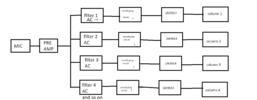
is the order of the block diagram in post #243 correct

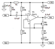
how do I go about designing the envelope circuit I realise that it can be done with a diode with a capacitor and a resistor

I also want to ability to use a jack instead of a mic via a chip as stated in post #29

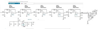
I'll just use this because it's precision and I'm all about precision and will enjoy putting together, for the opamps in the diagram can I use the TL074CN's that I already have, cheers. One thing I do want to know it how can you set the circuit up for reference ground comming from the buffer circuit, Please colud someone modify the image so that I can utilise REF ground please
1701358753403.png
 

Maglatron

Jul 12, 2023
2,025
Joined
Jul 12, 2023
Messages
2,025
so I can use the TL074CN for the pre-amp, I can the TL074CN the for filters, I can use the TL074CN for buffer circuit with the reference stage and that, I want to know if i can use the TL074CN in the - precision full-wave detector yay or nay? I also want to edit the circuit for it to run off the same REF gnd so I think the resistors and capacitors need swapping out! and would appreciate some help with that please

1701360339806.png
 

Attachments

  • Electret mic preamp.PNG
    Electret mic preamp.PNG
    6.8 KB · Views: 0
Last edited:

Maglatron

Jul 12, 2023
2,025
Joined
Jul 12, 2023
Messages
2,025
so alore
  1. Type:
    • TL074CN: Quad JFET-input operational amplifier.
    • LF353: Dual JFET-input operational amplifier.
  2. Pin Configuration:
    • TL074CN: 14-pin DIP (Dual In-line Package).
    • LF353: 8-pin DIP.
  3. Power Supply Voltage:
    • TL074CN: Typically operates from ±4V to ±18V.
    • LF353: Typically operates from ±4V to ±18V.
  4. Input Bias Current:
    • TL074CN: 30 pA (picoamperes) maximum.
    • LF353: 50 pA maximum.
  5. Input Offset Voltage:
    • TL074CN: 3 mV maximum.
    • LF353: 3 mV maximum.
  6. Common-Mode Rejection Ratio (CMRR):
    • TL074CN: 70 dB minimum.
    • LF353: 70 dB minimum.
  7. Open-Loop Gain:
    • TL074CN: 100 dB minimum.
    • LF353: 100 dB minimum.
  8. Slew Rate:
    • TL074CN: 13 V/µs typical.
    • LF353: 13 V/µs typical.
  9. Temperature Range:
    • Both typically cover the industrial temperature range of -40°C to 85°C.
  10. Noise Characteristics:
    • TL074CN: Not specified (depends on the specific model).
    • LF353: 18 nV/√Hz typical (input referred).
I think that it should be ok to use the TL074CH in place of the LF353!
 

Maglatron

Jul 12, 2023
2,025
Joined
Jul 12, 2023
Messages
2,025
how do I change the circuit to accomodate for the input bias current
Input Bias Current:
  • TL074CN: 30 pA (picoamperes) maximum.
  • LF353: 50 pA maximum.
these types of questions, I can't just search for on a search engine!
 

Maglatron

Jul 12, 2023
2,025
Joined
Jul 12, 2023
Messages
2,025
I want to modify the envelope detector circuit to run on virtual ground. I might need to swap out resistors and capacitors.
For this precision full wave peak detector, I need to alter the resistors and capacitors for +VS 12Volt -VS 0Volt, for reference ground and I'll be using a TL074CN for the operational amplifiers. Anyone think they can give it a crack?? the AD8031U1M will also be replaced with an operational amplifier in side of the TL074CN chip as will the LF535! 1st picture, EXAMPLE, 2nd picture is the one I want altering to have REF gnd (virtual ground), and 3rd picture is when The filter circuit has been changed to single supply, using a virtual ground reference: thanks in advance!!!
1701372979151.png
1701372955993.png
1701372927372.png
 
Last edited:

Maglatron

Jul 12, 2023
2,025
Joined
Jul 12, 2023
Messages
2,025
I noticed that when the filters have a reference voltage the last two filters out of the four swap around the values of the resistors and capacitors (in filterwizard). Because they are the same but not neccessarly the same order, is it that its the same outcome? do I just connect the grounds to the reference and use all of the same values of resistors and caps?
1701429510017.png
1701429486063.png
1701429092884.png
 
Last edited:

Maglatron

Jul 12, 2023
2,025
Joined
Jul 12, 2023
Messages
2,025
Why are the stages (A,B,C,D) not in order? all the stages stay the same!
 

Maglatron

Jul 12, 2023
2,025
Joined
Jul 12, 2023
Messages
2,025
Would this work?!? with all the op-amp TL074CN
 

Attachments

  • everything.jpg
    everything.jpg
    68.4 KB · Views: 2

Maglatron

Jul 12, 2023
2,025
Joined
Jul 12, 2023
Messages
2,025
I think that I pretty much have it sussed now, just need the last "Yes, that would work!" for my confidence
 
Top