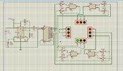
Traffic Signal DLD Project

Status
Not open for further replies.

Sadman

Dec 20, 2023
5
Joined
Dec 20, 2023
Messages
5
Hi,
I have constructed a 4 lane traffic signal design using logic gates in proteus, however, my project requirement is such that each road will only be open for vehicles for 30 seconds when the
green light is on. The yellow light
will be turned on for 5 seconds between the change of red to green or green to red in
any setting. I have used a 555 IC and 4017 Decade Counter, so I adjusted the timer IC in such a way that the green and yellow both remain on for 30 seconds. Now how do i design the circuit in such a way that the green is on for 30 seconds and while switching from green to red, the yellow is on for 5 seconds in between??? PLEASE HELP...
 

Harald Kapp

Moderator
Moderator
Nov 17, 2011
14,273
Joined
Nov 17, 2011
Messages
14,273
This looks like homework or an assignment. I therefore emoved i to the homework forum.
Here you'll find support to overcome obstracles, but we will not do your homework. Therefore show us your design so far. A schematic will help us understand your request better.

What is the on time for red? Probably also 30 s? Assuming it is also a multiple of 5 s, then your timebase should be 5 s (aka 1/5 Hz). Longer times for e.g. green or red can be achieved by different means. For example by combining more than one output of the counter via an OR gate to count multiple instances of the 5 s base interval.
 

Sadman

Dec 20, 2023
5
Joined
Dec 20, 2023
Messages
5
This looks like homework or an assignment. I therefore emoved i to the homework forum.
Here you'll find support to overcome obstracles, but we will not do your homework. Therefore show us your design so far. A schematic will help us understand your request better.

What is the on time for red? Probably also 30 s? Assuming it is also a multiple of 5 s, then your timebase should be 5 s (aka 1/5 Hz). Longer times for e.g. green or red can be achieved by differentz means. For example by combining more than one output of the counter via an OR gate to count multiple instances of the 5 s base interval.
 

Attachments

  • IMG-20231220-WA0000.jpg
    IMG-20231220-WA0000.jpg
    315.2 KB · Views: 14

Sadman

Dec 20, 2023
5
Joined
Dec 20, 2023
Messages
5
This is the circuit, when i simulate this, the green remains on for 30 seconds, now i want the yellow to be on for 5 seconds in between while switching from green to red in
 

Harald Kapp

Moderator
Moderator
Nov 17, 2011
14,273
Joined
Nov 17, 2011
Messages
14,273
The 555 runs at + 0.033 Hz or with a period of ~ 30 s. This is your timebase. You cannot achieve (at least not by reasonable means) a signal duration of 5 s with a timebase of 30 s.

As I mentioned above, you need to speed up the timebase to a period of 5 s. The you can change signals at an increment of 5 s or a multiple thereof (5 s, 10 s, 15 s, ...)
But with that scenario you can't use one output of the 4017 at a time as you currently do. Because then all signals will change in 5 s intervcalls.

I can imagine at least 3 comparatively simple methods (to be sure: there will be many other ideas, too):
  1. To achieve a longer duration than 5 s, connect multiple consecutive output signals of the 4017 by OR gates. For example by ORing Q3 and Q4 the resulting output Q34 = Q3 OR Q4 will be on for 10 s.
    Of course a single 4017 will not suffice to generate the required number of signal, so you will have to resort to cascaded 4017s (datasheet fig. 19)
  2. You can set up 2 555 timers, one for 5 s intervalls, the other for 30 s intervalls. Depending on the state of the 4017s outputs enable the one timer that generates the right period for this signal. You can use the RESET input of the 555 to disable or enable it.
  3. You can change the timing of the 555 on the fly using FSK (frequency shift Keying) as shown e.g. here. In the example on that website a second 555 is used as "pulse generator circuit" to modulate the frequency of the oscillator (FSK modulator) via a BJT Q. Replace the "pulse generator circuit" by the appropriate logic from the 4017s output signal to control the FSK oscillator for either 5 s period or 30 s period.
It's your choice.
 

Sadman

Dec 20, 2023
5
Joined
Dec 20, 2023
Messages
5
Can you please explain how do i connect the 2 timers with the decade counters and to the leds?
 

Harald Kapp

Moderator
Moderator
Nov 17, 2011
14,273
Joined
Nov 17, 2011
Messages
14,273
You can use a multiplexer to switch between two timers.Or you can use an OR gate when you use the reset pin method to start and stop the timers.
As for the LEDs: you've done that in your circuit. Where is the problem?
 

danadak

Feb 19, 2021
1,064
Joined
Feb 19, 2021
Messages
1,064
For future reference here is a way of doing traffic control with a
state machine. Stay with your current project, just tuck this
away in back of your mind for new possibilities.


Regards, Dana.
 

Sadman

Dec 20, 2023
5
Joined
Dec 20, 2023
Messages
5
Thanks a lot everyone, for your kind and genius suggestions!! I have successfully designed and run the schematic for the project!! ♥️♥️♥️
 

Ahmed456781

May 7, 2024
3
Joined
May 7, 2024
Messages
3
Designing a traffic signal system can be an interesting digital logic design (DLD) project. Here's a basic outline of how you could approach it:

Components Required:​

  1. Microcontroller or FPGA: You'll need a microcontroller or an FPGA to control the traffic signal operation.
  2. LEDs: Red, yellow, and green LEDs for each direction of traffic.
  3. Switches or Sensors: These will simulate the presence of vehicles at each direction.
  4. Power Supply: To power the circuit.

Basic Design Steps:​

  1. Define the Logic: Decide how the traffic lights will operate. Typically, it's a cycle of green light for one direction, then yellow, then red, while the other directions wait their turn.
  2. Create a State Diagram: Map out the states your traffic signal can be in and how it transitions between them. For example:
    • State 1: North-South Green, East-West Red
    • State 2: North-South Yellow, East-West Red
    • State 3: North-South Red, East-West Green
    • State 4: North-South Red, East-West Yellow
  3. Implement the Control Logic: Using your microcontroller or FPGA, write the code or design the logic circuits that will control the LEDs based on the current state and any inputs from sensors or switches.
  4. Interface with Switches or Sensors: Connect switches or sensors at each direction to detect the presence of vehicles. These inputs will influence the state transitions.
  5. Test and Debug: Simulate different scenarios and traffic conditions to ensure your system behaves as expected. Debug any issues that arise.

Additional Features (Optional):​

  • Pedestrian Crossing: Include pedestrian signals that change when a button is pressed.
  • Priority Control: Implement a priority system for emergency vehicles or public transport.
  • Traffic Density Detection: Use sensors to detect traffic density and adjust signal timings accordingly.

Safety Considerations:​

  • Ensure that there are proper fail-safes in place to handle unexpected situations, such as power outages or sensor failures.
  • Test the system rigorously to ensure it operates safely and reliably.

Implementation Notes:​

  • Depending on your skill level and available resources, you can implement this project using hardware (using discrete logic gates or microcontrollers) or software (using programming languages to simulate the logic).
  • There are various resources available online, including tutorials, sample code, and project guides, that can help you with specific aspects of this project.
Remember to document your project thoroughly and have fun experimenting with different designs and features!
 
Status
Not open for further replies.
Top