What are specs on this cap?

Stamey

Apr 28, 2023
44
Joined
Apr 28, 2023
Messages
44
I have a cap that has weird markings and I cannot tell what I should be measuring for. I found a spec in the manual for this magnetic brake, which the board came out of, that states 104J. The actual text from the manual:
C2 (Capacitor, CBB22, 400V, 104J)

Does that mean 104 Joules? How do I test this?
Which side is negative? I see no stripes or other markings to tell me.
See attached pics, please.

Thanks,
Chris
 

Attachments

  • 20240120_082003.jpg
    20240120_082003.jpg
    156.7 KB · Views: 5
  • 20240120_082022.jpg
    20240120_082022.jpg
    173.5 KB · Views: 5

Delta Prime

Jul 29, 2020
2,987
Joined
Jul 29, 2020
Messages
2,987
It's 1 microfarad capacitor the J stands for tolerance and happens to be equal to plus or minus 5%
 

bertus

Moderator
Nov 8, 2019
3,835
Joined
Nov 8, 2019
Messages
3,835
Hello,

The capacitor is an 100 nF or 0,1 uF 5% capacitor of 400 Volts.
Read this page for more info:

Bertus
 

Stamey

Apr 28, 2023
44
Joined
Apr 28, 2023
Messages
44
Thanks for the info! Mine measures 1.61 micro farads in one direction, and 2.3 micro farads the other way, but is trending down and was at 1.81 micro farads when I removed the test leads, as I did not know how long I should wait for the value to stabilize. Do the marking tell me which way to connect the test leads?
I suppose it is bad, since it is not 0.1 micro farads in either direction.

Thanks,
Chris
 

Delta Prime

Jul 29, 2020
2,987
Joined
Jul 29, 2020
Messages
2,987
Describe your test method please...
In case of non – polarized capacitor, connect it either way as they do not have polarity. Now, check the readings on the Digital Multimeter. If the multimeter readings are closer to the actual values (mentioned on the capacitor), then the capacitor can be considered as a good capacitor. Yours are far from good,replace the capacitor.
1705769540851.png

 
Last edited by a moderator:

Stamey

Apr 28, 2023
44
Joined
Apr 28, 2023
Messages
44
Sorry, I meant to mention, Fluke 77 IV, on capacitor test setting, leads to the solder joints on the board, as the cap is still mounted, but the board has been removed from the machine.

Thanks,
Chris
 

Delta Prime

Jul 29, 2020
2,987
Joined
Jul 29, 2020
Messages
2,987
You can remove one leg of the capacitor from the board desolder it and test that way or pull the entire capacitor off of the board itself desoldering it would be the best preferred way
Your meter is fluctuating because you are conducting an incircuit test other components are in parallel with that capacitor and that is what the meter is measuring. Only adding to confusion.
 

Stamey

Apr 28, 2023
44
Joined
Apr 28, 2023
Messages
44
OK, off the board, 101 nano farads, both directions, so I guess it's OK.
The situation is I am trying to troubleshoot a board that the manufacturer tech support says is bad, and they have a 3 month waiting period for the board. It is quite simple, I think, with 3 caps, two resistors, 1 diode, and 1 thyristor on it. There is another cap, but is is connected to the board by way of wires to a terminal block.
I am trying to determine if there is a bad component and replace it, saving me 3 months time.

Thanks,
Chris
 
Last edited:

davenn

Moderator
Sep 5, 2009
14,470
Joined
Sep 5, 2009
Messages
14,470
OK, off the board, 101 nano farads, both directions, so I guess it's OK.
The situation is I am trying to troubleshoot a board that the manufacturer tech support says is bad, and they have a 3 month waiting period for the board. It is quite simple, I think, with 3 caps, two resistors, 1 diode, and 1 thyristor on it. There is another cap, but is is connected to the board by way of wires to a terminal block.
I am trying to determine if there is a bad component and replace it, saving me 3 months time.

Thanks,
Chris

As we ask everyone .... Please show a photo of both sides of the board. make sure they are sharp and easy to read details
 

Stamey

Apr 28, 2023
44
Joined
Apr 28, 2023
Messages
44
All components of the board seem to be fine except for the thyristor. I have not yet been able to make a determination on this component.
The info I have is as follows:
The thyristor has "KS20A" on it, and "KS" on one of the flats of the hex. No other markings. No brand info on it.
I believe the the anode is the stud end, with the nut on it, the cathode is the long, covered lead coming off the top, and the gate is the small covered led coming off the top. They covered it with shrink tubing then folded it over and zip tied it. I suppose this is because of the 240V going through it. The component is still mounted on the board.
Resistance testing.
Test lead positive to anode, test lead negative to cathode: 280K ohms
Test lead negative to anode, test lead positive to cathode: Open
Test lead positive to anode, test lead negative to gate: 280K ohms
Test lead positive to gate, test lead negative to cathode: 107 ohms
Test lead negative to gate, test lead positive to cathode: 107 ohms
Does this determine one way or the other, the status of this thyristor, or do I need to concuct other test procedures?

Thanks,
Chris
 

Attachments

  • 20240121_091426.jpg
    20240121_091426.jpg
    150.4 KB · Views: 6
  • 20240121_091453.jpg
    20240121_091453.jpg
    162.8 KB · Views: 6
  • 20240121_091807.jpg
    20240121_091807.jpg
    101.1 KB · Views: 6

Delta Prime

Jul 29, 2020
2,987
Joined
Jul 29, 2020
Messages
2,987
OK, off the board, 101 nano farads, both directions, so I guess it's OK.
The situation is I am trying to troubleshoot a board that the manufacturer tech support says is bad, and they have a 3 month waiting period for the board. It is quite simple, I think, with 3 caps, two resistors, 1 diode, and 1 thyristor on it.
You have just proven this is not guesswork " troubleshooting that is...,"
My advice to you to take the capacitor off of the board was just a simple technique there are others for every individual component that we would all gladly share with you.What equipment did this come out of?
 

Attachments

  • KS200A.PDF
    141.6 KB · Views: 1
Last edited:

Stamey

Apr 28, 2023
44
Joined
Apr 28, 2023
Messages
44
This is a Baileigh Magnetic Sheet Metal Brake, BB-4816M. The normal operation is that when you turn it on, nothing happens. You put a piece of metal on top of the brake, sandwiched between a metal leaf, then pus the "Start" button. At that time, you are supposed to get about half the clamping power of the electro-magnet in the base, ~120v DC. When you begin to pull the bending leaf up, a micro-switch is triggered and the full clamping force is engaged, ~240v DC, until you put the bending leaf back down into the resting position. When you press the "Stop button the magnetism should be released, and holding the stop button for a few seconds, is supposed to engage a demagnetizing circuit to get the rest of the magenetism out of the work piece and leaf to make it easier to lift and remove the work piece.
It has two contactors in it, one should engage for the initial clamping (pressing the Start button) and the other should engage when you activate the micro-switch when pulling up the bending leaf. These are working when expected and stopping when expected.
The problem is that when I turn the power on it is immediately clamping, pulling a lot of current though the thyristor, even though the contactors are in the off position. Both contactors have been checked for sticky contacts and both are OK.
I am trying to figure out why I am getting 35v to the electro-magnet when I turn the power switch on, even though I should be getting nothing to the electro-magnet until I press the Start button.
The machine is rated for 12 amps at 220V AC, but mine is pulling about 15A when I turn the power on, and does not change when I push the start button, or when I move the bending leaf.
I have ~248v AC out of the wall here, and this machine is picky bout the supply voltage, therefore I have a buck-boost transformer in the line to bring the voltage down to ~216v AC. The reality is that the voltage coming out of the buck/boost is 98v on one leg and 118v on the other. Swapping the legs has made no difference in the behavior of the machine.
A pic of the entirety of the electronics is attached.

Thanks,
Chris
 

Attachments

  • 20240109_152208.jpg
    20240109_152208.jpg
    318.4 KB · Views: 6
Last edited:

kellys_eye

Jun 25, 2010
6,512
Joined
Jun 25, 2010
Messages
6,512
  • To test the SCR, connect the positive output lead of the ohmmeter to the anode and the negative lead to the cathode.
  • The ohmmeter should indicate no continuity.
  • Touch the gate of the SCR to the anode.
  • The ohmmeter should indicate continuity through the SCR.
  • When the gate lead is removed from the anode, conduction may stop or continue depending on whether the ohmmeter is supplying enough current to keep the device above its holding current level.
  • If the ohmmeter indicates continuity through the SCR before the gate is touched to the anode, it indicates that the SCR is shorted.
  • If the ohmmeter will not indicate continuity through the SCR after the gate has been touched to the anode, it indicates that the SCR is open.
 

kellys_eye

Jun 25, 2010
6,512
Joined
Jun 25, 2010
Messages
6,512
The problem is that when I turn the power on it is immediately clamping, pulling a lot of current though the thyristor, even though the contactors are in the off position. Both contactors have been checked for sticky contacts and both are OK.
I am trying to figure out why I am getting 35v to the electro-magnet when I turn the power switch on, even though I should be getting nothing to the electro-magnet until I press the Start button.
Has the wiring been changed at any time?

Have you tested the bridge rectifiers on the chassis?
 

Attachments

  • Screenshot from 2024-01-21 17-22-02.png
    Screenshot from 2024-01-21 17-22-02.png
    72.9 KB · Views: 2

Stamey

Apr 28, 2023
44
Joined
Apr 28, 2023
Messages
44
I'm gonna try to make this short, but here goes.
I bought this machine from a guy in another state last month. I saw it work fine in his body shop, before we loaded it. He did not use a buck/boost transformer, and apparently had not read how this machine requires its voltage in the manual. It did not move on the way back, but the trailer bounces around as you might expect.
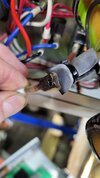
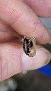
When I got home, I, knowing about the voltage issue, installed a buck/boost transformer before I powered it up in any way. The first time I ran it, I bent a piece of metal and it worked as expected. I then turned it off, not having project to bend at that moment. When I did get a project to work on I went to use it and found that when I plugged it in, it was on, regardless of the power switch. I found the power switch, double pole, single throw, was stuck ON, on one pole. I also noticed that the side that was stuck ON had heated up enough to start melting the rubber insulator around the female blade connector. I replaced the switch. Insulator was not melted enough to warrant action. I have not found any wire insulation damaged.
I have not changed any other wiring except to swap the legs around, and swap them back, and to replace one rectifier and the STOP switch, as instructed by tech support, with parts supplied by Baileigh.

Another thing that is baffling me is that when one leg of the supply power is moving 15A, the other leg is moving only 1.3-3A, yet the ground only has .3A on it. This is measured using a Fluke T6-600 inductive AC ammeter. I though that if you have one leg with X amps going through they other leg, or ground must have equal amps going through it. There is no neutral in the circuit.

I have also attached the manual for this unit, which contains a wiring diagram.

Thanks,
Chris
 

Attachments

  • 20240119_164147.jpg
    20240119_164147.jpg
    182.3 KB · Views: 5
  • 20240119_164203.jpg
    20240119_164203.jpg
    150.1 KB · Views: 5
  • MagBrakeManualBB-4816M_6-2016.pdf
    2.9 MB · Views: 5

Stamey

Apr 28, 2023
44
Joined
Apr 28, 2023
Messages
44
So, any ideas on finding this thyristor? Searches only provide sources in China, and they don't seems to be the exact same thing. I do not know how far from exact I can be on the various aspects of this component. Looking on Mouser, Digikey, and Newark, they do not seem to carry anything like this, at least with my limited knowledge on how to search for this on their web sites.

Thanks,
Chris
 

kellys_eye

Jun 25, 2010
6,512
Joined
Jun 25, 2010
Messages
6,512
The melted plastic on the spade connector seems to be from the dodgy switch contact causing arcing/heat and melting - nothing we haven't all seen before.

and to replace one rectifier and the STOP switch,
Polarity? What about the stop switch? Did you check the contacts
The problem is that when I turn the power on it is immediately clamping
Seems to me you got the wiring wrong on the STOP switch.
 

kellys_eye

Jun 25, 2010
6,512
Joined
Jun 25, 2010
Messages
6,512
Have you tested the thyristor according to the method I mentioned in #14?

The 'half clamping' voltage comes from capacitor dropper C4 and that may be dodgy. If it's gone short you'll always have full clamping.

If the thyristor tests faulty and needs replacing that's no real problem. The physical aspect is irrelevant although I appreciate your desire to replace like-for-like, getting a thyristor suitably rated - in a different package - is easy-peasy. You'd be looking for a STUD package device - here's a load of them:


Providing it has a max voltage rating of AT LEAST 400V you can pick one that is capable of carrying the maximum current (and then some) for your needs and I'd guess the OEM device marking means "20A" (it won't be 200V - too low) but ensure you get one of the right polarity in respect to anode-case or cathode-case. The datasheets applicable to the devices shown above are all beside the items.
 
Top