And I would just solder some jumper wires and all should be well, however, when I slide the contrast potentiometer most of the display lights up, I’m just hoping it’s not the graphics chipHave you tried applying light pressure along the edge of the ribbon that connects directly to the LCD itself (both on the board and at the LCD glass)? If you can 'encourage' more of the characters to appear you might get away with some added pressure using soft rubber strips at the pressure points. Not a permanent fix but a get-you-by.
As per the above, the display does look to be in the standard format and since the (off board) ribbon looks to be numbered it will likely match the same numbering scheme as the LCD advised.
Here you go, I see a few labels but not all of them are labeled
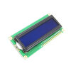
Get a clear close up shot of the rear side of the LCD with the (grey) ribbon cable and any markings on the rear of the LCD where the(grey) ribbon cable connects.
If you took the time to look at the links I showed of the basic 1602 LCD, you would see the terminal connections marked.
Point being, if the old original has markings, chances are they'll be the same and all that is needed is to connect new unit with the matching markings.
If not, then someone with experience in these should be able to work it out using any cross reference if different.
Note that RCL (marking on back of LCD) is an LCD manufacturer.
Guessing MBC16202 is a model number but obviously too old to get a search result.
Edit: I see the first photo, 16 pins are visible.
Whereas in the final shot of the LCD rear, only 14 are connected.
This might be quite normal as the last 2 pins of the 16 I quoted will be the on-board LED which the original does not have.(no problem)
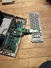
I mean, it’s a typewriter, I don’t need it functioning per say, a temporary fix is not necessary. I have several computers. But it’s cool to have, and put on a shelf somewhere, especially useful when my godforsaken printer decides to fudge up againHave you tried applying light pressure along the edge of the ribbon that connects directly to the LCD itself (both on the board and at the LCD glass)? If you can 'encourage' more of the characters to appear you might get away with some added pressure using soft rubber strips at the pressure points. Not a permanent fix but a get-you-by.
As per the above, the display does look to be in the standard format and since the (off board) ribbon looks to be numbered it will likely match the same numbering scheme as the LCD advised.
Crap, thought I was going to fix this easier then that.So I have messed around with LCD displays on a few occasions. Boat navigation displays, knot meters, depth sounders, LCD clocks, etc. The appearance of your display may indicate a voltage/current supply problem. You aren't getting enough of it to activate the segments/numerals on the display. I wouldn't mess with replacing or messing around with that display module quite yet. You might damage the ribbon cables. Before that, I would check the power supply circuit to that module. These display problems are often caused by failed/failing capacitors in that circuit. Look at those first.
Was hoping there were more markings than that, already well aware there were 14 pins and which way an ide socket is numbered but that wasn't the connection I was referring to.Here you go, I see a few labels but not all of them are labeled
If you include the info on model etc. perhaps it will help...?????? or is it a secret.?I will take a look, but I doubt the internet will have anything for me, this is a pretty rare machine.
You can probably find one that is selling just for parts.Use only as reference please....
No worries, Astro. Let's do the easy stuff first though. For now, take very clear photos of the front and back of the circuit boards in that thing. The larger one that is still in the machine and the smaller board the display module is connected to. It looks like the board in the machine is held in by screws. In the photos you take, try and concentrate on the electrolytic capacitors on those boards, but make sure all of the boards are shown. I don't know if you know what they (capacitors) are, so if not, let us know and we will help you.Crap, thought I was going to fix this easier then that.
It's an LCD fault.Are you familiar with visual signs of failure for capacitors?
It's an LCD fault.
If you look at the display photo in the first photo you'll see the same scan lines are missing in all.
Anyhow, I'll leave you to it.
Thanks, Bluejets, but Astro mentioned the majority of the display "lights up" when adjusting the "contrast potentiometer." This is the clue that leads me to believe the module is still functioning properly.And I would just solder some jumper wires and all should be well, however, when I slide the contrast potentiometer most of the display lights up, I’m just hoping it’s not the graphics chip
That's what the contrast does.majority of the display "lights up" when adjusting the "contrast potentiometer."