Hello everyone,
I am using the Analog Devices TMC5240 to drive a Sanyo Denki Sanmotion SM2564C20B41P bipolar stepper motor specs 2A/phase, 2.1 Ω/phase & 11mH/phase. I will be powering the stepper with 24Vdc @ approx. 2A.
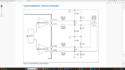
The data sheet (attached) for the Analog Devices TMC5240 stepper driver suggests that if using a high current that you should use an LC Filter between the driver & the stepper motor similiar to the image Attached.
The information they give to select the appropriate components is the wording below.
"A more elaborate scheme uses LC filters to decouple the driver outputs from the motor connector. Varistors V1 and V2
in between of the coil terminals eliminate coil overvoltage caused by live plugging. Optionally protect all outputs by a
varistor (V1A, V1B, V2A, V2B) against the ESD voltage. Fit the varistors to the supply voltage rating. The SMD
inductivities conduct full motor coil current and need to be selected accordingly."
Can anyone please help me in selecting the appropriate Inductors, varistors & capacitors for this LC filter?
Also has anyone used the Analog Devices TMC5240 stepper driver, I am hoping to control it with a Raspberry Pi 5 via SPI, I never used one of these drivers before. How do you go about connecting it to the RPI5?
I am using the Analog Devices TMC5240 to drive a Sanyo Denki Sanmotion SM2564C20B41P bipolar stepper motor specs 2A/phase, 2.1 Ω/phase & 11mH/phase. I will be powering the stepper with 24Vdc @ approx. 2A.
The data sheet (attached) for the Analog Devices TMC5240 stepper driver suggests that if using a high current that you should use an LC Filter between the driver & the stepper motor similiar to the image Attached.
The information they give to select the appropriate components is the wording below.
"A more elaborate scheme uses LC filters to decouple the driver outputs from the motor connector. Varistors V1 and V2
in between of the coil terminals eliminate coil overvoltage caused by live plugging. Optionally protect all outputs by a
varistor (V1A, V1B, V2A, V2B) against the ESD voltage. Fit the varistors to the supply voltage rating. The SMD
inductivities conduct full motor coil current and need to be selected accordingly."
Can anyone please help me in selecting the appropriate Inductors, varistors & capacitors for this LC filter?
Also has anyone used the Analog Devices TMC5240 stepper driver, I am hoping to control it with a Raspberry Pi 5 via SPI, I never used one of these drivers before. How do you go about connecting it to the RPI5?
") ).
).