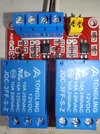
I had an error in Opto LED current needed. Eg. R2 value. Here is approximate
solution, based on what I think is Opto Coupler on your module.
One should do worst case, eg. lowest value of 12V supply, lowest
value of CTR in opto coupler, eg, margins, but try this out.
Note R4 is relay internal coil R, its not one you place in circuit, just a
value of the coil resistance in the relay.