Ryobi 4v cordless drill

spike1947

Feb 4, 2016
68
Joined
Feb 4, 2016
Messages
68
Hi
Sorry not been into electronics for quite awhile so a bit slow !.
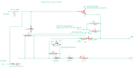
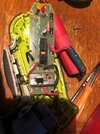
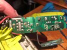
Have a Ryobi 4v cordless drill, problem not charging, voltage at input 6.2v!, what do I have to check in between ?.
have done a schematic, but not sure, if it is the correct way !.
Have done a schematic !
cheers
Spike
 

Attachments

  • PCB Ryobi 4v drill top.jpg
    PCB Ryobi 4v drill top.jpg
    316.8 KB · Views: 2
  • PCB Ryobi 4v drill bottom.jpg
    PCB Ryobi 4v drill bottom.jpg
    279.8 KB · Views: 2
  • Ryobi Drill 4v PCB.rev4...31.07.24.pdf
    17.5 KB · Views: 6

spike1947

Feb 4, 2016
68
Joined
Feb 4, 2016
Messages
68
Did a test from neg lead onto board and first pin on D1 and getting 6.7v then tested the other side of D1 , no voltage !,
 

Bluejets

Oct 5, 2014
7,374
Joined
Oct 5, 2014
Messages
7,374
Usually because the charger detects a dead battery. Test should be done with one of known good condition.
 

Delta Prime

Jul 29, 2020
2,987
Joined
Jul 29, 2020
Messages
2,987
Did a test from neg lead onto board and first pin on D1 and getting 6.7v then tested the other side of D1 , no voltage !,
What were you expecting? That's normal
You're using common ground. First pin on D1 is the anode(+) you're supposed to have voltage on there. The other side of D1 is the cathode(-) which is where your negative lead is connected to(common ground)so you just shorted your test leads....
The component circled in yellow does not look right to me, no gaps on a T-92 style package...
Didn't bother to look at your schematic....
photo_1722549098485.png
 

Delta Prime

Jul 29, 2020
2,987
Joined
Jul 29, 2020
Messages
2,987
Let that be a lesson to everyone, you have to see the schematics before you comment :cool: sorry I don't open PDFs,
 

spike1947

Feb 4, 2016
68
Joined
Feb 4, 2016
Messages
68
Usually because the charger detects a dead battery. Test should be done with one of known good condition.
Hi
Tks for your reply, yes did fit another Litho batt, was showing @3.95v !.

cheers
Spike
 

spike1947

Feb 4, 2016
68
Joined
Feb 4, 2016
Messages
68
Hi
I have this in a "Eagle" schematic, but the site won't let me upload that type of file !.

Spike
 

bertus

Moderator
Nov 8, 2019
3,835
Joined
Nov 8, 2019
Messages
3,835
Hello,

Make a screenshot of your schematic and upload the picture.

Bertus
 

spike1947

Feb 4, 2016
68
Joined
Feb 4, 2016
Messages
68
What were you expecting? That's normal
You're using common ground. First pin on D1 is the anode(+) you're supposed to have voltage on there. The other side of D1 is the cathode(-) which is where your negative lead is connected to(common ground)so you just shorted your test leads....
The component circled in yellow does not look right to me, no gaps on a T-92 style package...
Didn't bother to look at your schematic....
View attachment 64348
Hi
1: Thanks for your reply, not sure what I was expecting tbh, well I thought I would of got a full charger voltage reading or near enough !.

2: Sorry I don't understand what you are meaning "The component circled in yellow does not look right to me, no gaps on a T-92 style package".

3: Can you say why didn't didn't bother to look at my schematic ?.

cheers
Spike
 

Bluejets

Oct 5, 2014
7,374
Joined
Oct 5, 2014
Messages
7,374
Can you pls tell me what you think is incorrect ?.
Diodes, Led and transistors appear to be a-up as well as pos/neg from input.

More recent posts suggest the schematic is your interpretation so that explains many of the errors.
 

spike1947

Feb 4, 2016
68
Joined
Feb 4, 2016
Messages
68
Diodes, Led and transistors appear to be a-up as well as pos/neg from input.

More recent posts suggest the schematic is your interpretation so that explains many of the errors.
Hi
Tks for your reply, I have done the schematic had per what is on the pcb, will check again for any errors.
cheers
 
Top