Elite2 digi designer 115v to 230v

Diodeladder

Jul 27, 2024
18
Joined
Jul 27, 2024
Messages
18
New too the forum ,
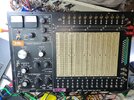
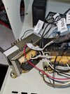
I have a elite 2 E&L instruments digi designer.

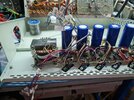
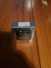
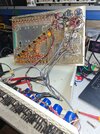
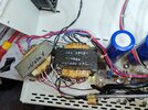
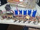
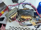
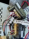
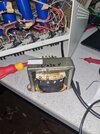
It currently doesn't appear to work at all , it has a uk plug installed but i have some of the orginal US plug. , there is 3 fuse holders 2 of which are blown , and 1 is missing , I have ordered a number of them to replace them At differing ampage , now I am assuming it is wired for 115 not 230v , I have included some pictures of it and the transformers , as I want to rewire it for uk power.

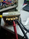
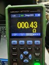
So far its not been going well finding any info on the transformers to make my life easier. , there is a part number on the top but it doesn't go anywhere when I searched for it. I had looked up a generic way of identifying the primary windings which didn't really make much sense as they where more geared up for 2 pin , not 4 or 6 , as I have 1 which is 4 pin and the other is 6 pin. ( probably not looking hard enough)
I have included some pics hopefully someone can shed some light or a shining beacon on this beast!
 

Attachments

  • 20240726_214729.jpg
    20240726_214729.jpg
    472.2 KB · Views: 7
  • 20240726_214944.jpg
    20240726_214944.jpg
    447.6 KB · Views: 7
  • 20240727_125158.jpg
    20240727_125158.jpg
    313.5 KB · Views: 7
  • 20240727_125921.jpg
    20240727_125921.jpg
    405.7 KB · Views: 6
  • 20240727_125902.jpg
    20240727_125902.jpg
    304.5 KB · Views: 6

Diodeladder

Jul 27, 2024
18
Joined
Jul 27, 2024
Messages
18
Following on from my post i isolated the transformers and powered only one of them which Is connected too the mains , I Dymo labelled everything to ensure I get it back in the right place , i then tried again , and it also blew that fuse. , my next test will be isolate the transformer and make sure its not shorting out.
 

Attachments

  • 20240727_225738.jpg
    20240727_225738.jpg
    282.3 KB · Views: 1
  • 20240727_233943.jpg
    20240727_233943.jpg
    247.3 KB · Views: 1

Diodeladder

Jul 27, 2024
18
Joined
Jul 27, 2024
Messages
18
Thanks I'll check it out. , it's near impossible to find the schematic for this beast, I did use some of Curiousmarc's video on one of these for aid but his one powered up this one up it without blowing the fuses . I had thought maybe the fuses where a little to low in taking the current , at this stage I am guessing... , I'll further my testing later and post further info as I find it. I'll be making a very basic schematic of the individual transformers , and move on too the boards eventually....
 

Diodeladder

Jul 27, 2024
18
Joined
Jul 27, 2024
Messages
18
Furthering on some testing and some head scratching. It would appear the transformer I isolated to get to work doesn't appear to work anymore , it popped the fuse and it also started to melt so it would appear this transformer isn't a usual one from the shelf today or have the same wiring as a usual one from the shelf today. , and it most definitely doesn't want to accept 230v ever even though it claims it can accept it. Before I tried getting it going a number of times, I did take some resistance measurements of the mains power poles. And 1-2 where around 3ohms , 3-4 where also around 3ohms there not that anymore... ( see pic)

When I measure the much larger one it has 4.74ohms going across the poles

It would appear that I'll have to find somewhere too rewind this transformer and hopefully bring it back from the dead.
 

Attachments

  • 20240728_211707.jpg
    20240728_211707.jpg
    276.1 KB · Views: 2
  • 20240728_212309.jpg
    20240728_212309.jpg
    193.9 KB · Views: 2
  • 20240728_212233.jpg
    20240728_212233.jpg
    246.1 KB · Views: 2

Delta Prime

Jul 29, 2020
2,987
Joined
Jul 29, 2020
Messages
2,987
Furthering on some testing and some head scratching. It would appear the transformer I isolated to get to work doesn't appear to work anymore
You're going to have to slow down you don't know what you're measuring and the results of that measurement would also be unknown, only leading to more confusion.
If you're planning to sell a product that you can use in Europe or in the United States then you will pick a transformer that has a dual primary winding.
Transformer with a dual primary windings (generally used to step down a series 220v or parallel 110v) If your utility Mains is 220v
Then you would connect the dual primary windings in series notice the polarity markings on the primary windings you hook them up just like batteries and they would add. Now you're taking it to United States so you would not connect the two primary windings together you would separate them, side by each ,meaning paralleled, it'll half the voltage making it 110V on the primary that connects to the utility mains. :)
photo_1722203581857.png
 
Last edited:

Diodeladder

Jul 27, 2024
18
Joined
Jul 27, 2024
Messages
18
You're going to have to slow down you don't know what you're measuring and the results of that measurement would also be unknown, only leading to more confusion.
If you're planning to sell a product that you can use in Europe or in the United States then you will pick a transformer that has a dual primary winding.
Transformer with a dual primary windings (generally used to step down a series 220v or parallel 110v) If your utility Mains is 220v
Then you would connect the dual primary windings in series notice the polarity markings on the primary windings you hook them up just like batteries and they would add. Now you're taking it to United States so you would not connect the two primary windings together you would separate them, side by each ,meaning paralleled, it'll half the voltage making it 110V on the primary that connects to the utility mains.
Hello
I don't see any markings , or are you referring too the numbers on the side ?

The way it was connected up ( before I started messing with it )

Was

Pin 1 to 3
Pin 2 to 4 incidently a large fan was connected too that winding...

Pin 1 to 3 where connected too the outlet.

In that setup it has blown a few or 2 , I wanted to isolated the transformer to mitigate any damage I wanted to ensure that it was the transformer at fault not a wrong wiring touch somewhere, the small bulb works fine so that's a relief, I then removed all the wiring from the transformer, and also from the primaries so connected pins 1-4 to the mains , according a generic transformer , with pins 2-3 bridged. The previous wiring was pretty much a generic wiring for dual use , it simply didn't work. I figured it doesn't work anyway I'll just make it worse probably.
Surprisingly it actually worked and the fan ran Unbelievably... but not for long. It blew the fuse again and now is dead completely, I think I just finished it off from the previousowners handy work , I'll send off the transformer for rewinding and I might even send the other one to ensure its ok and also get it identified by a professional. So when it's going back in I know what I am looking at.
 

Bluejets

Oct 5, 2014
7,374
Joined
Oct 5, 2014
Messages
7,374
It currently doesn't appear to work at all
Firstly, did it work before you opened it up or have you actually seen it working previously?
If so, what has changed to render it unworkable?
Did you plug it in to 240v while it was arranged for 115v operation?

Transformers are usually fairly sturdy beasts and with fuse protection I doubt any transformer winding problems would arise from a higher voltage BUT never say never.
When testing for suspected shorts that blow fuses, best to use a series mains tungsten style lamp.

I am not at all familiar with whatever multimeter it is you are using there but you say the primary readings are 3R on both sets on the small transformer which is wayyyyyyy too low. I imagine you had it disconnected completely during these tests?

One would expect to see at least 20 ohm dc resistance there.

There are conflictions as your multimeter shows 0.43R on 200R range, auto ?....but then it appears to have mV selected? ...what is that all about?

Perhaps start with a basic $10 analog style meter and set to ohms.
Fancy meters can trip you up and above all, not necessary.

The two black leads disappearing from the small transformer "appear" to be possible mains connection but who knows as only you can see that part.
Same with black leads off other tappings on the larger transformer, who knows where they originate.

An accurate and labelled hand drawn schematic would be helpful.
 
Last edited:

Diodeladder

Jul 27, 2024
18
Joined
Jul 27, 2024
Messages
18
Firstly, did it work before you opened it up or have you actually seen it working previously?
If so, what has changed to render it unworkable?
Did you plug it in to 240v while it was arranged for 115v operation?

Transformers are usually fairly sturdy beasts and with fuse protection I doubt any transformer winding problems would arise from a higher voltage BUT never say never.
When testing for suspected shorts that blow fuses, best to use a series mains tungsten style lamp.

I am not at all familiar with whatever multimeter it is you are using there but you say the primary readings are 3R on both sets on the small transformer which is wayyyyyyy too low. I imagine you had it disconnected completely during these tests?

One would expect to see at least 20 ohm dc resistance there.

There are conflictions as your multimeter shows 0.43R on 200R range, auto ?....but then it appears to have mV selected? ...what is that all about?

Perhaps start with a basic $10 analog style meter and set to ohms.
Fancy meters can trip you up and above all, not necessary.

The two black leads disappearing from the small transformer "appear" to be possible mains connection but who knows as only you can see that part.
Same with black leads off other tappings on the larger transformer, who knows where they originate.

An accurate and labelled hand drawn schematic would be helpful.
No it never worked when it arrived too me , it had a UK plug on it already and a snipped peice of a US plug with it. 2 fuses blown and 1 fuses missing, most of the chassis screws missing aswell ( good start) before I did any kind of testing and changing I labeled everything, and ensured the transformers could accept 230v I of course spotted the obvious writing on the top and assumed yes it can , as there is No docs for this device it is very difficult to perform any tests , and assume its telling me the truth , but I carried on , so I thought I'll isolate the only transformer which is connected too the mains , the other transformer daisy chains off the transformer i had isolated. , if I disconnect everything except the fan it'll run and I'll know if it works. , which it did , it was quite the fan was good but it popped the fuse and never ran again. That was the end of that transformer. As there is 2 in there I didn't want the same fate and that one was never powered so I am going to assume that's no good either and I'll have to send them away for rewinding or maybe they have something avaliable on the shelf that I can swap them out with and get this beast of a bread board going once again. I'll draw out a schema of what I know so far and upload It for you , also when I took some resistance readings from the main primaries (4pin end mains ) across pins 1-2 it claimed around 3ohms across 3-4 it claimed around 3ohms BEFORE I powered anything or did any testing, now when I found a generic picture and some details of a dual transformer much like the picture delta prime has supplied , which suggested much the same thing , if I want a dual use transformer the primaries have to be wired in a certain way which they where BEFORE any I isolated any wiring was this is how it arrived to me. (previous pictured) but it didn't work , there is a number of ways I could connect the transformer to the mains so I figured if it doesn't work then what's the harm the previous owner probably has blown it anyway. So I got going on having alook. , ill make a call today ( Monday ) and find out what and hopefully get this monster working once again.
 
Last edited:

Bluejets

Oct 5, 2014
7,374
Joined
Oct 5, 2014
Messages
7,374
You appear to be jumping to conclusions all over without any substantial test or proof.

Just trying to read your description with poor layout and grammar is enough to make my head spin.

It is obvious you are way in over your head and some assistance from a local technician would be advised.

Even trying to guide you through a series of tests I can see as being no point really as I asked several questions which remain unanswered.
 

davenn

Moderator
Sep 5, 2009
14,470
Joined
Sep 5, 2009
Messages
14,470
So I got going on having alook. , ill make a call today ( Monday ) and find out what and hopefully get this monster working once again.

You are going about this in the most difficult way

Go out and buy an external step down transformer from your local electronics supplier (230V in and 120V out)
They usually have an American socket on one side of them so that you can plug your device into it

Do Maplin or similar still operate in the UK ?

this one is an overkill for the power it can supply, am sure you will find something on your amazon, ebay or elsewhere
that supplys around 100 - 200Watts max for half the price


Dave
 

Bluejets

Oct 5, 2014
7,374
Joined
Oct 5, 2014
Messages
7,374
Go out and buy an external step down transformer from your local electronics supplier (230V in and 120V out)
They usually have an American socket on one side of them so that you can plug your device into it
No point if , as the Op says, existing transformer primaries measure out at 3 ohm a piece.
I tend to think the measurements were done incorrectly.
 

Martaine2005

May 12, 2015
5,276
Joined
May 12, 2015
Messages
5,276
I would expect low ohms on a transformer. Even as low as 0.5. After all, it’s just a coil.
Maplin do have some online bits n pieces but nothing to write home about.
 

Bluejets

Oct 5, 2014
7,374
Joined
Oct 5, 2014
Messages
7,374
3 ohm dc resistance does not seem anywhere near high enough for a small transformer.
I would expect something more like , as I sad previously, 20 dc ohm resistance to give the required ac impedance for operation.

Below is just one example for 220v ac.
https://sound-au.com/articles/xfmr4.htm
 

Diodeladder

Jul 27, 2024
18
Joined
Jul 27, 2024
Messages
18
so following on from the previous posts i have made. there has been some progress , . , so the transformer in question which was a dual power transformer 155 & 230v which was indeed setup for 115v not 230v , so i was going the right way about it even though wasn't explaining it very well , i had indeed re-wired it correctly for 230v , i think when i did get it to work , for the brief moment , i just finished it off. in the mean time i emailed , called , multiple companies many of them where not intrested. , eventually i did found a rewinding company locally which will rewind it for a reasonable amount , that way I'll know the output voltages t to find some more modern alternatives , i have also requested for a screen to be retained on the new one. to lower keep the noise low. , I'll be doing the same thing for the second larger transformer. I'll update once its done roughly a week.
 

Diodeladder

Jul 27, 2024
18
Joined
Jul 27, 2024
Messages
18
A follow up , I have eventually had the shorted transformer reverse engineered and is now brand new. Very happy. Its not installed just yet but it will be tomorrow.

In the mean time I rewired the second larger transformer to take uk power , I assumed the Worst when i powered it up.....and nothing.... no elaborate noise or strange loud hum well sort of the usual hum was so low I had to turn everything off in my workshop to even hear it , it was incredibly quite but it was on ( good start), anyway. I tested the secondaries and nothing, no dc voltage, not even a blip... I thought maybe does it Need the screen bolted too the earth strap to work? . Nope still nothing. , again I assumed the Worst , I started packing away and thought hang on I'll try ac and low behind the 3 secondary out puts are 16v 34v & 34v ac and all is working. Perfect!

I'll update as I go!
 

Attachments

  • 20240816_205142.jpg
    20240816_205142.jpg
    344.7 KB · Views: 2
  • 20240816_210648.jpg
    20240816_210648.jpg
    134.3 KB · Views: 2
Top