Elite2 digi designer 115v to 230v

Delta Prime

Jul 29, 2020
2,987
Joined
Jul 29, 2020
Messages
2,987
You're thread your the boss.
If you have any other questions don't hesitate to ask.... :)
 

Diodeladder

Jul 27, 2024
18
Joined
Jul 27, 2024
Messages
18
A Necromancer,brings monsters
Back from the living dead.
I like that!
We will be here for you...
Well the language I was using earlier on when resoldering the wires back onto the larger transformer could be construded as talking in tongues , and summoning somthing from the depths! It got abit hot with the soldering iron....
 

Diodeladder

Jul 27, 2024
18
Joined
Jul 27, 2024
Messages
18
I have now installed the new transformer, it appears too be working its producing 2 +12v output , & x2 -12v on the secondary outputs, But the rest of it doesn't appear to be. I put a scope across the function generator and its a weird mess of a signal across all 3 function sine , square & saw , aswell as the pulser none existent. The onboard power supply is producing nothing , now the fault finding can begin.
 

Delta Prime

Jul 29, 2020
2,987
Joined
Jul 29, 2020
Messages
2,987
now the fault finding can begin.
O. K. Its your fault.(just kidding)
If possible, please provide a photo of the waveforms as well as your O'scope settings .
You're unit is Circa 1970's - all electrolytic capacitors must be replaced they literally dry up.
 

Diodeladder

Jul 27, 2024
18
Joined
Jul 27, 2024
Messages
18
O. K. Its your fault.(just kidding)
If possible, please provide a photo of the waveforms as well as your O'scope settings .
You're unit is Circa 1970's - all electrolytic capacitors must be replaced they literally dry up.
Yes certainly I am using a portable scope instead of my bench one , as I feared ground loop affect through the outputs
 

Diodeladder

Jul 27, 2024
18
Joined
Jul 27, 2024
Messages
18
Yes certainly I am using a portable scope instead of my bench one , as I feared ground loop affect through the outputs
While i was on lunch I planned on getting some measurements from the outputs and there was some magic smoke coming from the back of the main board. , what I didn't notice a row of 4-5 transistors close too the edge of the board 1 of them was completely twisted round and bridging all 3 pins , I have a number of transistors in stock, so I might be lucky and the one that's in there crosses over to what I have. Ughhh....
 

Delta Prime

Jul 29, 2020
2,987
Joined
Jul 29, 2020
Messages
2,987
If at first you don't succeed.
Do it, like the electronic engineer
told you to do it, in the first place.
;)
 

Diodeladder

Jul 27, 2024
18
Joined
Jul 27, 2024
Messages
18
If at first you don't succeed.
Do it, like the electronic engineer
told you to do it, in the first place.
;)
Presented one complete terrible picture of the offending transitor row , the one closest in the edge was completely twisted around. No clue how that happened I hadn't even touched the main board with my sticky mits yet. , possibly happened in transit as it was in bits when it arrived to me.

So I don't have these transistors in stock.
They consist of PN5134'S & PN5121's

I found a 2N5134 , I haven't cross referenced the 2N with the PN yet to see if there the equivalent , also in my fairchildbook , and behold! It has the circuit diagram of the wave generator for this device!
 

Attachments

  • 20240819_200656.jpg
    20240819_200656.jpg
    190.2 KB · Views: 1
  • 20240819_202203.jpg
    20240819_202203.jpg
    299.8 KB · Views: 1
  • 20240819_202153.jpg
    20240819_202153.jpg
    211.7 KB · Views: 1

Diodeladder

Jul 27, 2024
18
Joined
Jul 27, 2024
Messages
18
Update 07/09/2024 (ignore the first post for some annoying reason it adjusted the places of where the pictures are)

update 07/09/2024 I'm having some trouble uploading the pictures in the correct places on the post, they all seem to want to bunch up and take all the explanations with it.

apologies for not updating i have damaged one of my eye's which is making it challenging doing any kind of tinkering.... but still i tried..

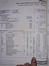
i have completely removed the main board from the chassis so i can attempt to power it up on the bench , but first i needed to know what voltages the board requires, which is not an easy task, i checked Ken Shirriff's blog on the elite 2 that Curiousmarc managed to bring back to life, that of course didn't really say anything other then it has 12v & 32plus minus, but it doesn't say if that is what the main board has that aswell... so i had to perform some measurements myself and hope the power supply is producing the correct power for the main board.

you'll see some of the shown voltages are minus this is due to not knowing what the colour codes are in one of the outputs they where not red or black, the where orange and grey, red and brown

this was the usual colours wires red + and black -
that produced 12v-+
https://ibb.co/SxVpsVF
https://ibb.co/RDmfbxs


there was a brown wire which i had tested which produced as above i had the probes round the wrong way. but again i wasn't sure as this digi designer does - voltages so who knows eh!
https://ibb.co/MpSvjnG
https://ibb.co/Kj8K2Nk


then i tested the Orange and Grey wires which produced
https://ibb.co/ZfT53vN
https://ibb.co/T12vZ8y


then i tested the voltage going into the neon lamps as there was a some magic smoke coming from a resistor ( I'll cross that bridge later)
so i isolated the wiring and tested the voltage going in.
https://ibb.co/MPjhST8
https://ibb.co/K2vQdjR


that's as far as i have got with the elite2 , I'll have to see if i can find a quad power supply which can go up to them sort of powers. my dual power supply wont be able to power all three area's of the board successfully. as mentioned before i know its says minus voltages but you get the idea. my next task is isolate the neon lamps and try and repair the damage but gradually bring the voltage up to see what it wants and or check the comparators and see what they operate at maybe that could give me a clue.

the fun continues.
 
Last edited:
Top