Connecting two buck boost boards for a split supply?

Tinkerer99

Aug 25, 2024
6
Joined
Aug 25, 2024
Messages
6
Hi folks,
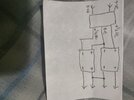
Just bought a cool buck boost converter which i'll power from a laptop power supply.
Would there be a problem if I powered two of these and connected the +ve output of one board to the -ve output of the other to have a split supply?
Thks17246111716311168615574438561069.jpg
 

bertus

Moderator
Nov 8, 2019
3,835
Joined
Nov 8, 2019
Messages
3,835
Hello,

The drawn setup will only work when the converters are fully in/out isolated.

Bertus
 

Tinkerer99

Aug 25, 2024
6
Joined
Aug 25, 2024
Messages
6
Can I use a multimeter to figure out if the lines are isolated? If so, how?
 

Delta Prime

Jul 29, 2020
2,987
Joined
Jul 29, 2020
Messages
2,987
On non-energized equipment
Resistance check! If input common &
Output common are connected than
thay are not isolated.
Quick,Dirty Inaccurate,
 

Bluejets

Oct 5, 2014
7,374
Joined
Oct 5, 2014
Messages
7,374
What voltage split are you aiming to get and at what load current?
Do you have a link to the specs of the board you show?

Point being it may be possible to use just the one board, run to output up to 30v (for say a 15v split) then add a couple of linear regulators positive and negative along with a couple of capacitors and create a zero volt rail that way.

Still need to isolate from original input common overall.
 

Tinkerer99

Aug 25, 2024
6
Joined
Aug 25, 2024
Messages
6
On non-energized equipment
Resistance check! If input common &
Output common are connected than
thay are not isolated.
Quick,Dirty Inaccurate,
Resistance between in/out common was 760k. Then I measure the + in/out and I got 2k resistance increasing up to 12k over 10 seconds. Guess something was charging up. Then I went back to the ground common and now it read open circuit.
Can I assume it is isolated?
 

Harald Kapp

Moderator
Moderator
Nov 17, 2011
14,270
Joined
Nov 17, 2011
Messages
14,270
Can I assume it is isolated?
You can assume what you like, but it is highly unlikely that this module is isolated. Tell us the make and model (or a link to the datasheet or the website where you purchased this module) so we can have a more detailed look at the module.
 

Delta Prime

Jul 29, 2020
2,987
Joined
Jul 29, 2020
Messages
2,987
Resistance between in/out common was 760k.
I would expect greater than 1 Mega ohm isolated resistance both power rails for floating (again isolated outputs).make,model,year of your unit under test. Please.
 

Delta Prime

Jul 29, 2020
2,987
Joined
Jul 29, 2020
Messages
2,987
Then I measure the + in/out and I got 2k resistance increasing up to 12k over 10 seconds. Guess something was charging up
Again Quick,Dirty ,Inaccurate
It works for me because I know what to expect.
I Apologize for any confusion I my have caused you....
I'm still learning how to convey information.
 

Tinkerer99

Aug 25, 2024
6
Joined
Aug 25, 2024
Messages
6
You can assume what you like, but it is highly unlikely that this module is isolated. Tell us the make and model (or a link to the datasheet or the website where you purchased this module) so we can have a more detailed look at the module.

Low cost Chinese stuff. Bought a couple of days ago via Amazon. The item box had model dp60 label on it.
 

Delta Prime

Jul 29, 2020
2,987
Joined
Jul 29, 2020
Messages
2,987
An isolated buck converter (Fly-Buck) uses a synchronous buck converter with coupled inductor windings to create isolated outputs.
I see nothing to sugest the use of this topology. I sumitt your outputs are not isolated,therefor can not be used for your application.
 

bertus

Moderator
Nov 8, 2019
3,835
Joined
Nov 8, 2019
Messages
3,835
Hello,

The two large chips are a processor and a lcd driver.
The two small chips cant be read.

I assume the converter is not isolated, so you can not connect the outputs in series.

Bertus
 

Tinkerer99

Aug 25, 2024
6
Joined
Aug 25, 2024
Messages
6
Thanks Delta, Bertus, and Harald,

How about this? What if I create a mid-voltage rail using discrete components at the input, like a virtual 0ve rail, creating a split supply? See pic? Wouldn't that work?
 

Attachments

  • 17247793587454360468176665641320.jpg
    17247793587454360468176665641320.jpg
    201.1 KB · Views: 6

Bluejets

Oct 5, 2014
7,374
Joined
Oct 5, 2014
Messages
7,374
I doubt (as quoted previously) that the input/output is common isolated....so once again.....no.
 

Harald Kapp

Moderator
Moderator
Nov 17, 2011
14,270
Joined
Nov 17, 2011
Messages
14,270
Hello,

The two large chips are a processor and a lcd driver.
The two small chips cant be read.

I assume the converter is not isolated, so you can not connect the outputs in series.

Bertus
+1. No transformer, no isolation.
 

Tinkerer99

Aug 25, 2024
6
Joined
Aug 25, 2024
Messages
6
Thks for all the replies,
Last attempt... Each converter gets its own separate linear power supply (transformer, bridge rect, smoothing cap).
Now surely....!! ??
 

Bluejets

Oct 5, 2014
7,374
Joined
Oct 5, 2014
Messages
7,374
Possibly...if you keep the outputs totally isolated from everything else.
It really depends on what your final application is and there may well be some regulation problems or other so far unseen.

Why don't you just buy a split supply unit?
Cannot understand why some will bend over backwards just to be different, no matter on the possibly complexity of the outcome.
 
Top