Inductive load issue (?) makes MCU go hard fault

dacair

Sep 4, 2024
13
Joined
Sep 4, 2024
Messages
13
Hello,
I'm new on this forum, I could not think where to ask support, so I just googled "electronics forums" ... I hope I got in the right spot.
I'm not expert electronics engineer although I'm a CNC/Robots integration engineer. In our job we do not do electronics but rather we connect and program industrial devices.

I have made schematics and code for a vacuum pump controller that is controlling the pressure in a vacuum chamber using a vacuum pump and measure the pressure with an absolute pressure sensor. We use this system in our hobby to vacuum bag / laminate different composites for RC airplanes and drones that we build and fly ourselves.

The controller is made using a STM32F103C8 MCU, GY68 module ( BMP180 pressure sensor ) and an 1.3" OLED display. The pump is a 3 phase 0.18kW supplied from 2 phase 220V (VEVOR 1/4 HP pump).

All tests work fine, the electronics and code, as long I do not connect the motor ( to controller terminals ).

If I connect the motor the controller goes in hard fault and halts at a certain point when the motor is swithced on. So it's kind of randomly but when the relay switches the motor on.

Innitially I used only the switching power supply 220Vca/5Vcc and supply also the controller but later I added a AMS1117 module in the circuit but the issue is still there.
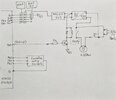
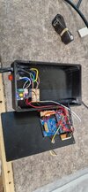
I attached pictures with a schematic (it also shows where wires are connected ) and with the 3D printed box with the electronics.

I suppose It's something about inductive loads that is creating this behavior.
Can anyone help with some suggestions - what can we try do in order to avoid this behavior?

Thanks,
Cristian
 

Attachments

  • VACUUM1.jpg
    VACUUM1.jpg
    251 KB · Views: 11
  • VACUUM2.jpg
    VACUUM2.jpg
    292.2 KB · Views: 11

danadak

Feb 19, 2021
1,063
Joined
Feb 19, 2021
Messages
1,063
I assume you are not paralleling the 220/5V supply with the ASM1117 as show in schematic ?

A DSO is a terrific tool to look for transients on pins/supplies. One shot level trigger on supply pin,
set for ~ .7V above supply + edge, -V at cpu low V - trigger and see what you get.

When using DSO make sure you are careful around HV line stuff :

https://download.tek.com/document/02_ABCs-of-Probes-Primer.pdf isolation/floating measurments

Does CPU hang ? Where does it halt in code, can you tell ?

All pins not terminated in low Z suspect. Unused pins set as outputs.

Bypass caps should be ceramic disk .1 uF paired with low esr tants, like polymer
tants.

1725488248244.png

Regards, Dana.
 

Harald Kapp

Moderator
Moderator
Nov 17, 2011
14,271
Joined
Nov 17, 2011
Messages
14,271
Possibly interference from the motor via the power supply of the controller. An EMC filter on the 220 V input side of the 5 V power supply migt help mitigate the issue.
To verify it is the motor and not the relay circuit: disconnect the motor from the circuit, then operate the circuit. What happens when the relay is activated? Does the circuit go on working as expected or does it stall? In teh first case, the motor is very likely the issue. In the second case the motor can't be the issue as it is out of the circuit. Then you'll have to inspect the construction of the relay part of your circuit. Keep the high voltage side wires as far away as üpossible from the low voltage side. Add an electrolytic capacitor > 100 µF directly from the + side of the relay coil to GND (G1) as the relay may draw a significant inrush current which may cause the 5 V supply to dip noticeably, thus interrupting the operation of the MCU.

As a note o the side: it is imho not a good idea to set up PB9 with an internal pull-up. This may cause the NPN transistor to conduct while the software does not explicitly drive PB9 low (e.g. during startup of the MCU). I suggest you cahnge this to pull-down to shut of the NPN transistor definitely.
 

dacair

Sep 4, 2024
13
Joined
Sep 4, 2024
Messages
13
Thanks for your help,

I assume you are not paralleling the 220/5V supply with the ASM1117 as show in schematic ?
I do supply the circuit side of the relay coil and transistor from 5V. Do you suggest is better I should supply from 3.3V ?

A DSO is a terrific tool to look for transients on pins/supplies.
I will have to purchase an oscilloscope to perform these tests

Does CPU hang ? Where does it halt in code, can you tell ?
Yes the CPU halts, it goes into a hard fault loop (function). I can test later today see in which function goes or if goes always in the same one.

All pins not terminated in low Z suspect. Unused pins set as outputs.
Do you mean I should not set unused pins as outputs? I left the unused pins as they are by default in the CubeMX.

To verify it is the motor and not the relay circuit: disconnect the motor from the circuit, then operate the circuit.
When the motor is not connected all works fine.

Keep the high voltage side wires as far away as üpossible from the low voltage side.
The 220V and relay board are on the bottom side of the box while the MCU board is on top of the box.

As a note o the side: it is imho not a good idea to set up PB9 with an internal pull-up.
Thanks, I've changed PB9 output to pull-down.

What I'm thinking to do:
- Per Haralds suggestions, add a capacitor >100uF from the + side of the relay coil to GND and find an EMC filter on the 220 V input side of the 5 V
If these does not resolve the issue:
- Take the relay board and all motor cables out of the box.
- Supply the 5V from an external power supply - similar to smart phones ( not sure they are better ).
 
Last edited:

danadak

Feb 19, 2021
1,063
Joined
Feb 19, 2021
Messages
1,063
Do you mean I should not set unused pins as outputs? I left the unused pins as they are by default in the CubeMX.

General recomendations :

1725569315958.png

On relay transient current (typical relay) :

1725569439010.png

As you can see relay current is basically inductive, so not particularly fast. And todays regulators
load transient response can manage that demand and stay in regulation, check the transient res-
ponse for the one you are using. Note this sim done with just 1 uF on 5V buss. If you are using
LDO then consult its datasheet, and additional constraint is output cap has to haver a min ESR
for stability considerations.


Regards, Dana.
 

dacair

Sep 4, 2024
13
Joined
Sep 4, 2024
Messages
13
I appreciate your feedback.
I have to tell I thought I missunderstand some basics... .
It's a CPU board controlling a relay that switches a motor on/off ...
Personally I thought this has been solved (or resolved ) at modules (boards) level (long time ago) so I may have not selected the right config/modules.
I still need to find the right modules to sort this out... as I'm not planning going on researching new ways for it ... I may change everything, add a contator for the motor and separate electronics from load (the motor) ... separated boxes
 

Harald Kapp

Moderator
Moderator
Nov 17, 2011
14,271
Joined
Nov 17, 2011
Messages
14,271
Personally I thought this has been solved (or resolved ) at modules (boards) level (long time ago)
Programming the correct I/O configuration is up to you. Set unused I/O-pins to OUTPUT (preferred for sensitive environments, see post 5) or activate the built-in pull-up resistors when left as INPUT pins.
 

danadak

Feb 19, 2021
1,063
Joined
Feb 19, 2021
Messages
1,063
I appreciate your feedback.
I have to tell I thought I missunderstand some basics... .
It's a CPU board controlling a relay that switches a motor on/off ...
Personally I thought this has been solved (or resolved ) at modules (boards) level (long time ago) so I may have not selected the right config/modules.
I still need to find the right modules to sort this out... as I'm not planning going on researching new ways for it ... I may change everything, add a contator for the motor and separate electronics from load (the motor) ... separated boxes
Personally I thought this has been solved (or resolved ) at modules (boards) level (long time ago) so I may have not selected the right config/modules.

The low cost module biz largely driven by Chinese, and the variation of everything from layout (grounds especially),
bypassing (no high freq .1 uF ceramic in parallel with bulk caps), and user wiring star versus delta grounds versus chained
grounds, coupled with fast processors, inductance, a recipe for issues.

Take ESP8266, ESP32 modules, use a DSO, look at supply rails, infinite persistence, edge trigger, AC coupled,
100 mV / box, and do not be shocked by anything from 200 mV pk - pk noise to .5V. Its ugly.

And bulk cap esr variation one manufacturer to another, we are talking parasitic salad, I learned to check even
RF performance of ceramics 50 years ago there was so much variation.

Your wiring frankly looks like a farm of antennae's. And a central common ground I cant identify.
Youtube and net lots of advice on grounding..... youtube this "analog ground and digital ground in pcb"

Regards, Dana.
 
Last edited:

danadak

Feb 19, 2021
1,063
Joined
Feb 19, 2021
Messages
1,063
From chatgpt :

For designing circuits involving microprocessors, including wiring and PCB layout, several application notes and resources can be extremely useful. Here are some recommended sources and types of application notes you might find helpful:

### **1. General Microprocessor Design:**
- **Microchip Technology’s Application Notes**: Microchip provides extensive documentation for their microcontrollers, including guidelines for PCB layout and wiring. Look for notes like "AN1186: Layout Guidelines for High-Speed Designs" and "AN1040: Microcontroller (MCU) PCB Design Guidelines".
- **Texas Instruments (TI)**: TI offers application notes such as "SLAA452: PCB Design Guidelines for High-Speed Digital Circuits" and "SPRAA28: Guidelines for Designing with TMS320C6000 DSPs".

### **2. Power Supply and Decoupling:**
- **Analog Devices**: They provide application notes such as "AN-100: High-Speed PCB Layout Techniques" and "AN-1067: Power Supply Decoupling for High-Speed Analog and Digital Systems".
- **Maxim Integrated**: Look for notes like "MAXIM APPLICATION NOTE 3604: Power Supply Bypassing and Decoupling".

### **3. Signal Integrity:**
- **Keysight Technologies**: Application notes like "Keysight: Signal Integrity Basics" offer insights into maintaining signal quality and integrity.
- **Rohde & Schwarz**: They have various notes on high-speed PCB design and signal integrity, which are valuable for microprocessor-based designs.

### **4. Layout Guidelines:**
- **National Semiconductor (now part of TI)**: Look for "AN-2024: PCB Layout Guidelines for High-Speed Digital Design".
- **Altium**: Altium provides application notes and whitepapers such as "Best Practices for High-Speed PCB Layout" which are useful for modern PCB design.

### **5. Specific Microprocessor Application Notes:**
- **ARM**: For ARM-based microprocessors, ARM provides detailed application notes and design guidelines. Check ARM’s official website or their partners' sites.
- **Intel and AMD**: For Intel or AMD processors, the respective manufacturer’s documentation and design guides can offer insights into specific requirements and best practices.

### **6. General PCB Design Resources:**
- **IPC Standards**: IPC-2221 and IPC-7351 are industry standards for PCB design which provide comprehensive guidelines on layout and design practices.
- **Online Design Communities**: Websites like Stack Exchange, EEVblog, and Reddit's r/PCB provide real-world advice and solutions to common PCB design issues.

### **7. Books and Textbooks:**
- **"High-Speed Digital Design: A Handbook of Black Magic" by Howard Johnson and Martin Graham**: A classic text on PCB layout techniques.
- **"PCB Design for Real-World EMI Control" by Bruce Archambeault**: Focuses on PCB design with an emphasis on electromagnetic interference (EMI) control.

These resources should give you a solid foundation for designing and laying out PCBs involving microprocessors. Each provides a different perspective or focus area, from general principles to specific techniques and guidelines.
 

dacair

Sep 4, 2024
13
Joined
Sep 4, 2024
Messages
13
Thanks for the links and information.
I think still this is a simple control layout ... basically willing to control one relay with a NPN transitor. I told in a previous post - there are no issues if I do not connect the motor to the relay.

For safety I'll add a 470uF capacitor between + side of the relay coil and ground but I'm not sure that is the problem. I've made some other project in past using the same circuit and never had issues...

I will focus on reasons why adding the motor through the relay contacts affects so much the supply of the MCU. It's otherwise strange as long I supply the MCU through a switching power supply that is isolated from 220V via a transformer. So way to go is :
- change the 5Vdc power with a better quality one or change it with one that is on the plug side.
- Move the relay of the motor in another box - if the issue is "a farm of antennae's" in the circuit:)
- add an optocoupler in the ciruit beforeon transistor.

I was away for couple of days but tomorrow or Moday will spend some time on it.
Any suggestions are welcomed.

Thanks
 

Delta Prime

Jul 29, 2020
2,987
Joined
Jul 29, 2020
Messages
2,987
For safety I'll add a 470uF capacitor between + side of the relay coil and ground

Flyback Diode, also known as reverse EMF diode,free running diode. Is what you meant to say.
Capacitor in parallel with the relay coil,I use in AC circuits to compensate for reactance with capacitor values in the nF.
You're using DC circuit any driver you use for the relay coil could be damaged or destroyed by introducing a electrolytic capacitor.
1725706033138.png
 
Last edited:

danadak

Feb 19, 2021
1,063
Joined
Feb 19, 2021
Messages
1,063
Three problems :1725707374425.png


1) On power up cap, with no charge on it, looks like a short so relay turns
on even though Q1 is off.

2) Q1 experiences large current spike discharging that cap when "normal"
relay command is turned on.

2) Significant power spike in Q1 discharging cap.

Problem you have is not knowing actual source of problem, so throwing
large C at problem and unable to observe electrically it solves problem
for all T and V environmental changes is marginal solution possibly.

Without a adequate scope to track down root of problem bit of a crap shoot.
I have been there before, no decent scope, so sympathetic to what you
are facing.

Beauty of a DSO is you can set it for single shot trigger, trigger on a V that
is out of spec, and see/capture if you get V's on control components, like
processor, that are issues. And the infinite persistence mode used on a supply
rail or a rail being measured will capture aperiodic problems that are out
of spec V's, like a supply rail. Can be an eye opener.

One possible way of getting around the no DSO problem is use a comparator
and a F-F/LED combo, and set comparator to trip V to see if you get any out
of spec triggers. Even this requires tight ground and supply issues, in old magazines
use to be logic probes you could do this with. Look for one that has a adjustable
threshold design, possible on youtube DIY version.


Regards, Dana.
 
Last edited:

Harald Kapp

Moderator
Moderator
Nov 17, 2011
14,271
Joined
Nov 17, 2011
Messages
14,271
Flyback Diode, also known as reverse EMF diode,free running diode. Is what you meant to say.
No, read carefully. The diode has been there from the beginning.
The capacitor is not parallel to the coil but from the coil's "+" to GND, thus buffering the power supply when the realy is turned on.
 

dacair

Sep 4, 2024
13
Joined
Sep 4, 2024
Messages
13
So, I got a PC osciloscope Hantek6022BE. I connected the controller to CubeIDE so I capture what hard fault occures
I changed the 5V powersupply with a better one, I remved 3V3 stab and supplied the MCU on 5V point, I changed power supply wiring with thicker and shorter wires. Made one GND point from where I connect to MCU, and the other devices.
I connected the osciloscope on the 5V power supply at the coil + terminal and monitor the voltage... hope the Hantek is fast enough to trigger.

And now I seat since 45 min and no faults ... funny:D
 

dacair

Sep 4, 2024
13
Joined
Sep 4, 2024
Messages
13
Some feedback after all these changes...
I changed the code so that I've checked i2c comm's with OLED and BMP180 every ~ 1 sec's using the function HAL_I2C_IsDeviceReady( ... ) .

It still does not works fine, but now the MCU does not goes in hard fault - I think that change of the power supply and better wiring sorted that part out. Will still continue monitor anyway ...

But now I'm left with a new identified issue - I suspect this was in all the way. The pressure at random moment in time makes a reading of 1750 mBars while normal reading is max 1010 mBar (at my altitude) and after that, the BMP180 does not responds anymore ... see picture. I got this same behavior 4 times today and no other.

I would suspect fist the length of the cable - so how long a shielded cable for a good I2C for a safe connection ?? Or may be SCL and SDA with individual shielding would help?
The cable that I used is a shielded USB cable I removed connectors and made the i2c connections with dupont on MCU side, soldered on BMP180.

As measures to resolve this:
- remove dupont connectors and solder the connections on MCU side
- reduce the length of cable - 40-50 cm ( that would be minimal to our need )

*Now I can see some small light at the end of the tunnel ... thanks for supporting me

20240908-1.PNG
 

Harald Kapp

Moderator
Moderator
Nov 17, 2011
14,271
Joined
Nov 17, 2011
Messages
14,271
reduce the length of cable - 40-50 cm
I²C was developed for inter-board communication and thus for rather short bus lengths. If the bus length exceeds 10 cm, special measures should be taken, see this specification by NXP, specifically chapter 7.5. Use the slowest possible data rate for longer bus lines. Do you have a bypass capacitor from Vcc to GND directly on the sensor? Providing a good supply is essential.

after that, the BMP180 does not responds anymore
Can you soft-reset the sensor if that condition occurs?
 

dacair

Sep 4, 2024
13
Joined
Sep 4, 2024
Messages
13
Can you soft-reset the sensor if that condition occurs?
That is an idea to recover from the fault ... BMP180 data sheet says:
1725862601803.png


see this specification by NXP, specifically chapter 7.5.
Thanks for providing this reference as well the once in the previouse posts ... very useful in the future as well ...


* But there is another alternative - add a STM32G03 ( 26x18mm ) connect the BMP180 to it and setup a basic serial comm with the main MCU. This is because talking into our groups about this struggle, one said he would like to have a device (system??), when mine is working ( that's no bussines oportunity anyways ... :p). Then I have to ensure some reliability.
 
Last edited:

danadak

Feb 19, 2021
1,063
Joined
Feb 19, 2021
Messages
1,063
What rate are you trying to read the BMP180 ? The datasheet discusses conversion
time versus mode. In the mS area. Hi res almost 100 mS....

Hantek :

1) Set it for edge trigger, AC, say 100 mV, infinite persistence, and give it a minute
of acquisitions to see what your peak to peak noise is on 5V.

2) Now set it for Vss - 1 V (one trial), then Vdd + 1V, edge again, DC vertical mode,
single shot trigger, and see if you can capture any transients. Do that on varies pins,
say I2C, again power rail, inputs, etc.. Note make sure its sampling rate is full 48 MS/s.

Make sure ground lead on probe short length. Probe set to 10X to minimize Cload of probe.


Note its a tad slow for todays stuff, like the ST Micro, but should give you some indication and for
1 channel work should be adequate sample rate.

Regards, Dana.
 
Last edited:
Top