Sir Yvautrin . . . . . . .
No you do not.
As already stated, charger for nimh and lipo or li ion are completely different.
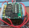
Not true . . . . . IF . . . . .his new BMS will be taking an
ADEQUATE DC input voltage from the chargers raw DC supply (of which, its present mere 7 VDC is being waaaaay too low).
And then, the BMS will be distributing a proper constant current charging and auto cut off of the new Li Ion pack . . . which I believe that it WILL.
Now Yvautrin, (ya' know whuts ? my Spell Cheks thanks that youse shud be named . . . . . neutrino ?
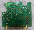
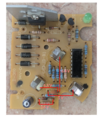
I need your visual inspection of that Bosch AL1411 charger . . . . and I would have also REALLY liked . . . a good photo of the foil path side of the board . . . for me to able to "read" it.
Initially I see wires pilled from X1 and X2.
Probably will be receiving raw 12?-----15?------18?'ish VAC from a hefty plug in wall wart transformer. Since this chargers spec sheet says it will be charging at a 1 amp and then dropping down to a 50 ma trickle charge level after a full charge is achieved.
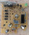
MY OBSERVATIONS AND PERCEIVED CIRCUIT DESIGN . . . . . . as available . . .to date . . .viewed data limits permit!
AC comes in at X1 and X2goes into the four side by side discrete 1N4002 FWB configured diodes, to give raw DC.
The ONLY filtering of that I then see, is that bucolic 47-100 ufd E-filter at bottom left corner of the board;
SOOOOOOOOOO with typically 1000 ufd min desired capacitance, for a minimally filtered DC level of 1 Ampere pull . . . . . I'm seeing pulsating DC going to those battery cells .
Thereby I'm expecting that sole E- cap relating to a power supply for the control electronics.
Somehow, I'm expecting that sole 16 pin I.C. to be a CD4060 . . . . which is a binary counter with a built-in oscillator. It can be used to produce selectable time delays or different frequencies.
Its RC oscillator configuration is probably using that sole small brown disc ceramic C2 and oscillates at a high audio frequency and divides down to minutes or hours at downstream Q outputs , if so configured for that specific time .
I times out a charge and eventually shifts down into trickle charge.
SOOOOOOOOO . . . .you wanna help me, in being my eyes and testing and filling in questions ?
THEN getting that original charger supplying your Li Ions voltage needs without external cobbling.
INITIALLY NEEDED INFO . . . . .
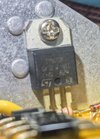
Look at that large heat sinked black transistor ? ? or I.C. (which I really ??? guesstimate??? to be a LM317 adjustable 3 terminal voltage regulator OR Constant current source. What does its markings tell us ?
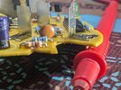
Hook up the wall wart to get AC into the unit at X1-X2 and measure that AC voltage
Measure and post the DC voltage being read across the small E cap and give its labeled capacitance and DC voltage rating.
ALSO do an AC voltage check of that just prior voltage to see if AC ripple of pulsating DC is a problem at present minimal / no loading conditions.
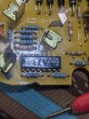
All of your part ID numbers seem to be obscured by their parts being mounted atop them . . . . .
Just aside, right of the E-cap, see the 500mw glass diode . . . . .I suspicion it to be a 6-8-9 zener diode, used for supplying low voltage DC for this boards discrete transistors, 1 green LED and that 16 pin I.C.
Power up board and do DC metering across that diode - meter lead to left side and + lead to right . . .banded . . . side and give voltage reading
measured.
Keep - meter probe on . . . . or back to . . . . the small E-caps negative and + probe to the two boards facing plug in connectors. Expecting them
to be the charger power outputs into yout battery pack . Tell us their polarities. After determining the - polarity, keep that - lead there and test with the + meter lead to the side plug in terminal with a black blob marking to its side. Any voltage ?
Now what I really think . . . . . . is that terminal is the secret to your charger . . . . . being able to flawlessly RECOGNIZE which battery packs of 5
different voltages, has been plugged into this versatile charger unit.
In your disassemblage, of the original battery pack innards,
did you find ? a resistor being connected to this terminals countpart in the original state battery pack ?
CONFIRMATION . . . .
Your original battery pack was being STUFFED with 10? NI-MH cells and probably used 1800ma cells or upgraded to 2400ma cells if being a workmans HD unit
That would have 14VDC out with a full charge or 12VDC at mid level and 10VDC at near end of service.
Now, with your new Li Ion configured pack . . .you say . . .has 3 times 4.25VDC for 12.75VDC series cell output at full charge available at the batt terminals.
Use it somewhat, and at mid charge level 3 times 3.6VDC for 10.8 VDC output and finally after some use, until each cell drains down to cutoff level of 2.5VDC . . . . . or 3 times 2.5VDC for 7.5 VDC . . . . . THEN . . . . .your BMS unit should open conduction of a POWER FET in the battery negative supply line . . .thats all . . . . lights out.
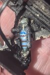
BTW . . . . .are your Li Ion cells being 18650 all metal cylindrical units ?
ARE WE HAVING FUN YET ? . . . . . . .talk to me !
73's de Edd . . . . .

.