Yamaha RX-V373 In protection

catsferguson

Oct 18, 2024
6
Joined
Oct 18, 2024
Messages
6
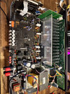
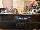
Hello, I have a RX-V373 receiver which I believe is turning off in protection.
This unit was working perfectly but wasn't used for a few months, and recently when I went to turn it on nothing happened.
I believe it is stuck in protection because when I hold tone control + straight the unit powers up for a split second and displays USB UPDATE, I assume this is the first setting in the diagnostic menu. However it immediately cuts off and will repeat this as long as those buttons are held down. This to me means it is capable of working and is not completely done for like a bad CPU.

I first opened it up and was just looking around and I unplugged the AC connection to the main board and it no longer immediately cuts of instead it takes about 3 seconds, I think this is a different protection of like abnormal voltage. In the manual it says if it cuts of on over current that it will be locked out until reset, this is what happened with everything connected. With the main board disconnected it cuts of after 3 seconds and the power button will work 3 or so times until it locks out needing to be reset.

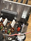
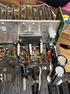
I have opened it up and completely disassembled expecting to find a bulging cap or something burnt but there is no visible damage. The only thing I have found is one of the large white resistors that I believe is meant to be 0.22 ohms is measuring 3.1k. I think if this is the correct measurements then there would be other damage around such as the SKA IC's but I am unsure about how to check.

Something I've noticed that I'm not sure if is right is the negative speaker terminals have 0 ohms to ground.

I'm stuck now and I don't know what to do from here any advice would be great.
Thanks for reading

This is the manual I'm using with the schematics and stuff: https://www.manualslib.com/manual/1082963/Yamaha-Rx-V373.html
 

Attachments

  • unnamed.jpg
    unnamed.jpg
    641 KB · Views: 6

Harald Kapp

Moderator
Moderator
Nov 17, 2011
14,280
Joined
Nov 17, 2011
Messages
14,280
Something I've noticed that I'm not sure if is right is the negative speaker terminals have 0 ohms to ground.
That's normal. See this connection on page 90 of the manual:
1729249027077.png
one of the large white resistors that I believe is meant to be 0.22 ohms is measuring 3.1k.
That could be one cause of failure as such resistors are used to sense current. With such a dramatic increase in resistance the sense circuit will imeediately go into overcurrent(protection) mode. What makes you think these should be 0.22 Ohm? Is this component labeled on te PCB? Something like Rxxx?
 

catsferguson

Oct 18, 2024
6
Joined
Oct 18, 2024
Messages
6
That's normal. See this connection on page 90 of the manual:
View attachment 65008

That could be one cause of failure as such resistors are used to sense current. With such a dramatic increase in resistance the sense circuit will imeediately go into overcurrent(protection) mode. What makes you think these should be 0.22 Ohm? Is this component labeled on te PCB? Something like Rxxx?
Hello, thanks for the reply. I think it is R48 and has 3 legs, yes, I think it says 3W, 2-0.22ohms it is quite hard to ready. The others that seem to be the same all match each other with 0.2ohms to middle leg and 0.4ohms end to end. Just this one which is the odd one out.
Oh right just seen that photo ahh I will try get a photo and have a look. I am a bit lost right now, i will have a think thanks.
 

catsferguson

Oct 18, 2024
6
Joined
Oct 18, 2024
Messages
6
Hello, thanks for the reply. I think it is R48 and has 3 legs, yes, I think it says 3W, 2-0.22ohms it is quite hard to ready. The others that seem to be the same all match each other with 0.2ohms to middle leg and 0.4ohms end to end. Just this one which is the odd one out.
Oh right just seen that photo ahh I will try get a photo and have a look. I am a bit lost right now, i will have a think thanks.
The one closest to the edge of board is the one im thinking about.
 

Attachments

  • unnamed (1).jpg
    unnamed (1).jpg
    402.6 KB · Views: 3

73's de Edd

Aug 21, 2015
3,730
Joined
Aug 21, 2015
Messages
3,730
Sir catsferguson . . . . . .
Indeed that is dual Decimal 2 ohm 3 Watt resistor . . . . R48 and is associated with coupling the audio output from one of three audio power amps within IC1 to your R and L + Center speakers.
That R48 resistor pair feeds your Front Right Speakers audio.
The center R49 resistor pair feeds your Front Left Speakers audio.
The left R33 resistor pair feeds your Center Speakers audio.
You have seen that HALF of that R48 resistor is showing a top side burn on it's white case.

Test from center lead to the end of the burnt side and expect high resistance . . . . as was originally compared to being a mere low two tenths of an ohm.
Then check from center wire to the resistors un burnt sides, wire end . . . . . I'm thinking that reading might still be at .22 ohm . . .am I right ?

AMASSED WORK SHEET SNIPPETS . . . .
Left mouse clickee-clickee makee 2 level of MAG up . . . . . . . . . . . . far left page clickee-clickee makee-makee return to forum page
1729376081006.png

SECTIONING . . . . .

TOP LEFT
quadrant is your photos snippet with R48 being within a YELLOW rectangular markup and its burnt 1/2 section within a RED markup
BOTTOM LEFT quadrant is R48 and same markups within its foil circuit board connections
TOP CENTER section is pin # indexing of I.C. 1 a (STK433-330N-E)
TOP RIGHT quadrant is affected parts list
BOTTOM CENTER AND RIGHT is relevant STK433 Data Sheet with my drawing/inserting in of the circuit positions of R48-R49 and R33 dual (Decimal) 22 ohm-3W resistors.
BLUE ANNOTATIONS of Center Channel parts
PINK ANNOTATIONS of Front Left Channel parts
YELLOW ANNOTATIONS of now PROBLEMATIC Right Channel parts

¿¿¿ WHUT DUN WENT AND HAPPENED-ED-ED ???
a la . . . . . . . . . . . . BLOW BY BLOW . . . . .

It seems to appear, that at some point in time, the dark half of R48 heated up and went open circuit. Look at the bottom/central Data Sheet and over at the RED STAR there is a POSITIVE polarity main amp power supply of high 30'sh VOLTS at 2'ish+ AMPS, that certainly can CRUNCH that mere 3 watt resistor 1/2 section of R48.
The same is true in the additional presence of a NEGATIVE polarity main amp power supply of high 30'sh VOLTS at 2'ish+ AMPS, and if unleashed, it could burn out the other half section of R48. but, by appearance, that does not seem to be the case.
This R48 malady could have occurred with the unit playing, or at an initial power turn on attempt?
One thing that was present at either of those possible conditions is a voltage sensing circuitry, sampling audio output to speakers and is connected to a speakers disconnect relay.
IF there is excess voltage on a speaker line, it either activates that relay to disconnect all of your speakers OR if being at power turn on, it never even lets the speakers get connected in.

INITIAL SLEUTHING . . . . .
You have your bad RIGHT channel and its 1/2 bad R48 and you have the other two channels and their unaffected dual .22 ohm resistors .

With an un powered unit . . .for days now . . . . and no stored P.S. capacitor charges lets do some exploratory OHMMETER tests.

INITIAL SET UP
Consulting the Data Sheet at its left top corner one can see that the RED STAR IC1 pin 3 goes to the "barn burning" POSITIVE POWER supply and travels across the top and drops down to feed each channels Collector connection of a darlington NPN Power transistor.
Make and keep one ohmmeter lead connection to that #3 terminal connection.
Take the other free ohmmeter lead and initially connect to IC1 terminal #4 and you will effectively be evaluating that transistors Collector-Emitter junction.
Log in reading experienced.
Then lift that same lead and move it over to IC1 terminal #6 and also evaluating that transistors Collector-Emitter junction.
Log in its reading experienced.

NOW . . . . there's being possible trouble, trouble right here in River City . . . . a la Lil' Abner . . . .

Then lift that same lead and move it over to IC1 terminal #18 and also be now evaluating " THE " R48 associative transistors Collector-Emitter junction.
Log in its reading experienced.
That last tests connection, is where the difference in comparison to the two other working channels will be expected/experienced.

NEXT . . . .lets move that first ohmmeter test lead from I.C. #3 and re connect to the also "barn burning" NEGATIVE POWER supply at IC1 pin #2

Consulting the Data Sheet at its left top corner one can see that the BLACK STAR IC1 pin #2 goes to the also "barn burning" NEGATIVE POWER supply and travels across the bottom and routes up to each channels Emitter connection of a darlington PNP Power Transistor.
Move and keep one ohmmeter lead connection to that #2 terminal connection.

Take the other free ohmmeter lead and initially connect to IC1 terminal #5 and you will effectively be evaluating that darlington PNP transistors Collector-Emitter junction.
Log in reading experienced.
Then lift that same lead and move it over to IC1 terminal #7 and then be evaluating that transistors Collector-Emitter junction.
Log in its reading experienced.
Finally . . . . move that flying ohmmeter lead to IC1 pin #19 to see if there is any difference, comparing to the prior two good/working transistor readings.

FINAL PERSPECTIVE . . . . .
Normally each channels dual resistor center point quiesces at 0 VDC and swings more + or - in accordance to input audio drive levels, with the respective NPN or PNP Power output increasing the positive or negative waveform nodes.
A Collector to Emitter crunch/short, brings the full fury of the supplies upon a resistor.

Thaaaaassssit . . . . . . I now do be . . . . . .
EatingPopcorn.jpg


Time to feed those logged down ohmmic readings back to me for evaluation . . . . . or . . . . . you . . . . with your infinite wisdom . . .may have already surmised a conclusion.


73's de Edd . . . . . . .

Bangkok.png
OOUUUUCCCHHH ! . . . . . . . .Dave . . . . .refer this one to your better half . . . .
.
 
Last edited:

catsferguson

Oct 18, 2024
6
Joined
Oct 18, 2024
Messages
6
Sir catsferguson . . . . . .
Indeed that is dual Decimal 2 ohm 3 Watt resistor . . . . R48 and is associated with coupling the audio output from one of three audio power amps within IC1 to your R and L + Center speakers.
That R48 resistor pair feeds your Front Right Speakers audio.
The center R49 resistor pair feeds your Front Left Speakers audio.
The left R33 resistor pair feeds your Center Speakers audio.
You have seen that HALF of that R48 resistor is showing a top side burn on it's white case.

Test from center lead to the end of the burnt side and expect high resistance . . . . as was originally compared to being a mere low two tenths of an ohm.
Then check from center wire to the resistors un burnt sides, wire end . . . . . I'm thinking that reading might still be at .22 ohm . . .am I right ?

AMASSED WORK SHEET SNIPPETS . . . .
Left mouse clickee-clickee makee 2 level of MAG up . . . . . . . . . . . . far left page clickee-clickee makee-makee return to forum page
View attachment 65027

SECTIONING . . . . .

TOP LEFT
quadrant is your photos snippet with R48 being within a YELLOW rectangular markup and its burnt 1/2 section within a RED markup
BOTTOM LEFT quadrant is R48 and same markups within its foil circuit board connections
TOP CENTER section is pin # indexing of I.C. 1 a (STK433-330N-E)
TOP RIGHT quadrant is affected parts list
BOTTOM CENTER AND RIGHT is relevant STK433 Data Sheet with my drawing/inserting in of the circuit positions of R48-R49 and R33 dual (Decimal) 22 ohm-3W resistors.
BLUE ANNOTATIONS of Center Channel parts
PINK ANNOTATIONS of Front Left Channel parts
YELLOW ANNOTATIONS of now PROBLEMATIC Right Channel parts

¿¿¿ WHUT DUN WENT AND HAPPENED-ED-ED ???
a la . . . . . . . . . . . . BLOW BY BLOW . . . . .

It seems to appear, that at some point in time, the dark half of R48 heated up and went open circuit. Look at the bottom/central Data Sheet and over at the RED STAR there is a POSITIVE polarity main amp power supply of high 30'sh VOLTS at 2'ish+ AMPS, that certainly can CRUNCH that mere 3 watt resistor 1/2 section of R48.
The same is true in the additional presence of a NEGATIVE polarity main amp power supply of high 30'sh VOLTS at 2'ish+ AMPS, and if unleashed, it could burn out the other half section of R48. but, by appearance, that does not seem to be the case.
This R48 malady could have occurred with the unit playing, or at an initial power turn on attempt?
One thing that was present at either of those possible conditions is a voltage sensing circuitry, sampling audio output to speakers and is connected to a speakers disconnect relay.
IF there is excess voltage on a speaker line, it either activates that relay to disconnect all of your speakers OR if being at power turn on, it never even lets the speakers get connected in.

INITIAL SLEUTHING . . . . .
You have your bad RIGHT channel and its 1/2 bad R48 and you have the other two channels and their unaffected dual .22 ohm resistors .

With an un powered unit . . .for days now . . . . and no stored P.S. capacitor charges lets do some exploratory OHMMETER tests.

INITIAL SET UP
Consulting the Data Sheet at its left top corner one can see that the RED STAR IC1 pin 3 goes to the "barn burning" POSITIVE POWER supply and travels across the top and drops down to feed each channels Collector connection of a darlington NPN Power transistor.
Make and keep one ohmmeter lead connection to that #3 terminal connection.
Take the other free ohmmeter lead and initially connect to IC1 terminal #4 and you will effectively be evaluating that transistors Collector-Emitter junction.
Log in reading experienced.
Then lift that same lead and move it over to IC1 terminal #6 and also evaluating that transistors Collector-Emitter junction.
Log in its reading experienced.

NOW . . . . there's being possible trouble, trouble right here in River City . . . . a la Lil' Abner . . . .

Then lift that same lead and move it over to IC1 terminal #18 and also be now evaluating " THE " R48 associative transistors Collector-Emitter junction.
Log in its reading experienced.
That last tests connection, is where the difference in comparison to the two other working channels will be expected/experienced.

NEXT . . . .lets move that first ohmmeter test lead from I.C. #3 and re connect to the also "barn burning" NEGATIVE POWER supply at IC1 pin #2

Consulting the Data Sheet at its left top corner one can see that the BLACK STAR IC1 pin #2 goes to the also "barn burning" NEGATIVE POWER supply and travels across the bottom and routes up to each channels Emitter connection of a darlington PNP Power Transistor.
Move and keep one ohmmeter lead connection to that #2 terminal connection.

Take the other free ohmmeter lead and initially connect to IC1 terminal #5 and you will effectively be evaluating that darlington PNP transistors Collector-Emitter junction.
Log in reading experienced.
Then lift that same lead and move it over to IC1 terminal #7 and then be evaluating that transistors Collector-Emitter junction.
Log in its reading experienced.
Finally . . . . move that flying ohmmeter lead to IC1 pin #19 to see if there is any difference, comparing to the prior two good/working transistor readings.

FINAL PERSPECTIVE . . . . .
Normally each channels dual resistor center point quiesces at 0 VDC and swings more + or - in accordance to input audio drive levels, with the respective NPN or PNP Power output increasing the positive or negative waveform nodes.
A Collector to Emitter crunch/short, brings the full fury of the supplies upon a resistor.

Thaaaaassssit . . . . . . I now do be . . . . . .
EatingPopcorn.jpg


Time to feed those logged down ohmmic readings back to me for evaluation . . . . . or . . . . . you . . . . with your infinite wisdom . . .may have already surmised a conclusion.


73's de Edd . . . . . . .

View attachment 65028
OOUUUUCCCHHH ! . . . . . . . .Dave . . . . .refer this one to your better half . . . .
.
Thank you so much, that was so helpful and I think you have nailed it. I have measured all of these now I believe. I actually don't think there is any visible burn on the resistor but you were absolutely right about being just the "burnt" part having high resistance. I think it looks burnt because of a shadow, but it also is inside. I think you must have x-ray vision, I will try get a better photo as well.
So from the leg near the IC1 to the middle is 0.3 ohms, and from the middle to the other side (towards middle of board) is 3.08 k ohms. Across the whole thing I get 3.1 k ohms.

Alright, from pin 3 on the IC1 to pin 4 I get 27 k ohms and to pin 6 I also get 27 k ohms, now to pin 18 I get 0.1 ohms. I think this confirms what you are saying.
With the negative power I also have the same thing, from pin 2 of IC1 to pin 5 I get 25k ohms, same with pin 7, but with pin 19 I get 0.2 ohms. This seem odd to me, both things failed, and the resistor only damaged on one side but both failed, my thinking would be one caused the other and the first one had time to cook the resistor and now it cuts off before the second can do anything.

I do have a diode test on my multimeter so I've tried to do that, a little unsure about how this works but these were my results.
With the black lead on pin 3 on IC1. To pin 4, 0.5V, to pin 6, 0.5V and to pin 18 I get 0.002V.
Now with the red lead on pin 2. I get 0.5V to pin 5, to pin 7 is 0.5V and to pin 19 I get 0.002V.

So, so far the resistor is cooked because the STK IC let all of the power through to the resistor. Why would the STK fail, I have been reading and they do seem go quite often but would there be a reason that this happened, or its just it getting old and failed by itself.

WOW, I just took another photo to post, I do think it does look burnt, I can only see this through the camera. That's crazy to me.

Thank you!
 

Attachments

  • unnamed (3).jpg
    unnamed (3).jpg
    265.4 KB · Views: 4
  • unnamed (2).jpg
    unnamed (2).jpg
    541.3 KB · Views: 6

73's de Edd

Aug 21, 2015
3,730
Joined
Aug 21, 2015
Messages
3,730
You say . . . . .
Why would the STK fail, I have been reading and they do seem go quite often but would there be a reason that this happened, or its just it getting old and failed by itself.
I say . . . . .
you just typically experienced yourself a . . . . .
! "SCHITT" HAPPENS !
Looks like you are now being in the replacement market of a
Dual .22Ω 3w wire wound power resistor and a
STK433-330N-E SANYO Hybrid I.C.
Plus
be SURE of no inter pin solder bridges on that I.C. install. + full flux clean off.
AND pull the main fuse and find a lamp or drop light that will accommodate an OLD SCHOOL incandescent 100 watt lamp and connect its two plug prongs to two clip leads that will then connect into the (removed fuse) clips.
Power up then, to see that you don't experience a FULL LAMP BRIGHTNESS . . . . . indicating an overload condition now being present

Sourcing of the dual 3w resistors . . . . .


Best you Google Search for the STK433-330N-E as its now sort of obsolete for new design incorporation, but you might find a
NEW OLD STOCK unit somewhere


1729432559296.png
.
 
Last edited:

catsferguson

Oct 18, 2024
6
Joined
Oct 18, 2024
Messages
6
You say . . . . .
Why would the STK fail, I have been reading and they do seem go quite often but would there be a reason that this happened, or its just it getting old and failed by itself.
I say . . . . .
you just typically experienced yourself a . . . . .
! "SCHITT" HAPPENS !
Looks like you are now being in the replacement market of a
Dual .22Ω 3w wire wound power resistor and a
STK433-330N-E SANYO Hybrid I.C.
Plus
be SURE of no inter pin solder bridges on that I.C. install. + full flux clean off.
AND pull the main fuse and find a lamp or drop light that will accommodate an OLD SCHOOL incandescent 100 watt lamp and connect its two plug prongs to two clip leads that will then connect into the (removed fuse) clips.
Power up then, to see that you don't experience a FULL LAMP BRIGHTNESS . . . . . indicating an overload condition now being present

Sourcing of the dual 3w resistors . . . . .


Best you Google Search for the STK433-330N-E as its now sort of obsolete for new design incorporation, but you might find a

NEW OLD STOCK unit somewhere


View attachment 65034
.
Alright, thank you so much for your help. I will get these two parts and post how it goes. (shipping probably take 4 weeks to NZ haha)
Yes, I've seen people doing that so ill do that too. Thank you.
 

catsferguson

Oct 18, 2024
6
Joined
Oct 18, 2024
Messages
6
Hello, I've made some progress. I have put the new STK in and replaced the 0.22 resistor but have encountered another problem. I now shuts off on protection from PS PRT 043L. I can get into no protect mode and I hear the relays put in. The voltage on PS_PRT where it connections on the operation 2 board is 0.510V. Measuring this I went from J1331 to the chassis.
From looking in the service manual I think this in somehow taken from 7 different places. I have measured these and as far as I can tell they are all doing ok. I am worried that I may have measured some wrong however.

ACL = 41.6V AC From Blue to Blue and measuring individually I got 20.8 to both to the chassis.
AC2 = 31.62V AC Blue to blue and both 15.8 to the chassis
+-12A = 12V and -11.96V, I am slightly unsure about this one, I measured at J1315 and J1329 on opp 2 board.
+7D = 9.12V DC from J1318 to J1317, this is the same at the connector the the digital board. This seems rather high to me for +7 but I've seen other people with the same readings.
+5A = 4.95V DC at CB131 to ground
+5U = 5.8V at CB136 to ground, I cant find +5U anywhere but I found +5.5U and this is what I've measured.
-VP = -39.59V DC at CB136 to ground

If I have measured these right then I am very confused about what is happing. Maybe somewhere down the line from where I measured is low but I don't see that.

One thing that I found that seems wrong is IC133,IC134 and IC135 are very hot to the touch, now the unit was on for a while and they do not have the screws in that go into the heatsink but I did put thermal compound on them and they had good contact to heat sink.

I also connected laptop and it detects it, and shows RX-373 on the laptop and when I go to the same HDMI input on the receiver it does light up saying HDMI. The USB port also does charge things.

I do have a small voltage at the speaker outputs with a higher level on the center channel, I did not write this down but I think it was about 0.3V DC and on the center 0.5 maybe. This dropped to zero with a speaker connected however.

Thanks
 

Attachments

  • IMG_1782.jpg
    IMG_1782.jpg
    319.1 KB · Views: 6
Top