Transformer overvoltage

aeronaut

Dec 19, 2024
1
Joined
Dec 19, 2024
Messages
1
Greetings,

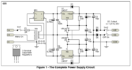
I'm building a variable voltage power supply using Rod Elliott's circuit from Elliott Sound Products audio. It all came together well, except when I plug it in, the 25-25 volt dual output on the transformer, after rectification, produces an output voltage of 41.2 V. Since I want to regulate with LM317 and LM337, which have an absolute maximum input voltage of 40 V, this is a small problem. A previous version of the circuit burned out the adjust/feedback resistors.

I've thought about using a zener between the rectifier and the regulator to limit the voltage, but I'm having trouble with the calculations, as there is no formal resistance on the source side of the zener, and I worry about the current through it getting crazy high. It will self limit at some point, but I want to make sure that point is before failure.

Any advice appreciated. A screenshot of the circuit is attached, attribution to Rod Elliott, from sound-au.com, specifically https://sound-au.com/project44.htm
 

Attachments

  • VVPS.png
    VVPS.png
    103.9 KB · Views: 10

bertus

Moderator
Nov 8, 2019
3,835
Joined
Nov 8, 2019
Messages
3,835
Hello,

Using a zener in series, all current must pass the zener.
Have a look at the tracking regulator on the following page:

Bertus
 

crutschow

May 7, 2021
984
Joined
May 7, 2021
Messages
984
Have a look at the tracking regulator on the following page:
One thing to be aware of is that the tracking regulator has near the full voltage across it in the event of an output short to ground.
 

crutschow

May 7, 2021
984
Joined
May 7, 2021
Messages
984
Here's a tracking preregulator using a high-voltage MOSFET and Zener, that will tolerate an output short.

1734636952431.png
 

jason022

Dec 31, 2024
1
Joined
Dec 31, 2024
Messages
1
Overvoltage in transformers can be caused by various factors, such as lightning strikes, switching surges, or issues with load balancing. Prolonged overvoltage can lead to insulation breakdown, overheating, and reduced lifespan of the transformer.

If you're dealing with overvoltage issues, it's crucial to ensure proper grounding, install surge protection devices, and have the system inspected by a professional.


[Mod edited to remove advertising link]
 
Last edited by a moderator:

Bluejets

Oct 5, 2014
7,374
Joined
Oct 5, 2014
Messages
7,374
Overvoltage in transformers can be caused by various factors, such as lightning strikes, switching surges, or issues with load balancing. Prolonged overvoltage can lead to insulation breakdown, overheating, and reduced lifespan of the transformer.

If you're dealing with overvoltage issues, it's crucial to ensure proper grounding, install surge protection devices, and have the system inspected by a professional.
Transformers typically go high on no or low low current just as they will go low voltage on overloads.
Doesn't mean there is any fault, just they are being operated outside of their design parameters.
 
Last edited by a moderator:

WHONOES

May 20, 2017
1,242
Joined
May 20, 2017
Messages
1,242
You must bear in mind that the specified output voltage of a transformer is at full load.
All transformers have a regulation factor expressed in percent (%) and varies greatly depending on its size and VA rating.
The regulation factor on a small device can be a large as 25% or more whereas larger types will be in the order of 2 to 3% or less.
Having said all that, manufacturers don't always express the regulation factor in the same manner so a little bit of interpretation may be required.
The essence of all this is that a 10V transformer for example with 10% regulation will be at 12.5V with no load. This also assumes that the input Voltage is exactly as specified by the manufacturer.
 

danadak

Feb 19, 2021
1,063
Joined
Feb 19, 2021
Messages
1,063

WHONOES

May 20, 2017
1,242
Joined
May 20, 2017
Messages
1,242
Correction to previous post. 10% of 10V is 1V not as inferred at 2.5V. So 10V transformer with 10% regulation would read 11V!!!!!!!.
 

Harald Kapp

Moderator
Moderator
Nov 17, 2011
14,271
Joined
Nov 17, 2011
Messages
14,271
the 25-25 volt dual output on the transformer, after rectification, produces an output voltage of 41.2 V.
The 25 V stated for the transformer are RMS. The peak value is [imath] rms \cdot sqrt 2[/imath] which evaluates to [imath]V_peak = 25 V \cdot 1.4142 \approx 35 V[/imath]. Add to that the regulation factor as shown by @WHONOES plus some overvoltage on the input (mains can have +-10 % tolerance or more, depending on where you live) and there you have the over 40 V you see.
Your most simple solution is probably using a regulator spec's for higher input voltage as posted by @danadak.
 
Last edited:
Top