Chrisraven4321
- Jan 1, 2026
- 15
- Joined
- Jan 1, 2026
- Messages
- 15
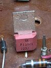
I have gotten myself into a 1975 Cordovox accordion with a separate amplifier and Tone cabinet. Fortunately I have finally acquired the complete schematics, unfortunately they have just the part numbers from Cordovox. I am trying to find out how to decipher, what a current or substitute part number would be from what is written on the part. An example is a transistor from GE and the number on it is P15000 with another number under it 7225, another one beside it has the number P15001 and the number under it is 7237. I believe it is in a regulator circuit. I can forward the schematics to anyone that is willing to give me a hand with this. I have an image of a component that looks like it is 4 diodes attached end to end, I am not familiar with this item unless it is just a stacked diode to give a certain voltage drop over the item??, I do have some decent test gear that is on my bench so I should be able to get readings and voltages that may be asked. (I have a 4 trace Teck Scope). I have attached one schematic which shows the power supply and I believe the transistors I referred to earlier are Q112 and Q114. I checked the voltages initially and it is saying I should have +and - 35 volts and I have + and - 40 volts. Q112 has a 20 volt zener at it's base and Q114 has a 22v zener at it's base. The output of Q114 is supposed to be -20 volts and I have -19 volts. The output of Q113 has an output of + 19 volts which is what it should be. Z4 is supposedly a 11 volt zener. I know I have a bunch of capacitors that are going to be replaced, in fact I think I will recap the whole project just to be safe. Looks like I have lots of leakers...lol. Looking forward to some help on my endeavor.
Thanks
Chris
Thanks
Chris

 ).
).