Need help in reverse engineering this power failure alarm circuit

divyanshl

Mar 15, 2026
3
Joined
Mar 15, 2026
Messages
3
Namaste,
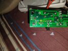
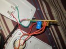
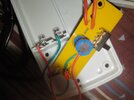
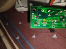
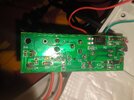
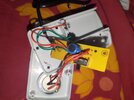
I need help to reverse engineer and get the schematic diagram and the BOM of a power failure alarm which has the attached circuit board. It runs on a 9V battery during power failure, and provides a 120db alarm aound output. Can anyone please provide any help.
 

Attachments

  • P_20260314_162620.jpg
    P_20260314_162620.jpg
    281.1 KB · Views: 15
  • P_20260314_162907.jpg
    P_20260314_162907.jpg
    163.2 KB · Views: 16

Martaine2005

May 12, 2015
5,276
Joined
May 12, 2015
Messages
5,276
I think you’ll be alone with this request.
Surely you can make a BOM yourself as it’s all in front of you!.
Apart from a few resistors, we can’t even see the markings of the ICs. Q1 and U4 especially.

What’s the need for reverse engineering this apparently simple circuit?.
Use a torch to shine on the back of the PCB and you’ll see what’s connected to what.
 

divyanshl

Mar 15, 2026
3
Joined
Mar 15, 2026
Messages
3
I think you’ll be alone with this request.
Surely you can make a BOM yourself as it’s all in front of you!.
Apart from a few resistors, we can’t even see the markings of the ICs. Q1 and U4 especially.

What’s the need for reverse engineering this apparently simple circuit?.
Use a torch to shine on the back of the PCB and you’ll see what’s connected to what.
Thanks for your response Martaine. The markings at Q1 and U4 have been etched out as is typical in chinese manufactured circuits. This is why I needed the help primarily. I'm struggling here to figure out this circuit because of that reason. I've used AI to figure out what Q1 and U4 are, but whatever it suggested(LM555, LM393, NE555, LM2903, MC34063) do not work in U4.
I must admit that I am no expert at this.
 

Delta Prime

Jul 29, 2020
2,987
Joined
Jul 29, 2020
Messages
2,987
Could you take another photo at a different angle of Q1 & U4 I do see some markings on it.
also, can you determine the working DC voltage of the blue electrolytic capacitor? if you look on the side of that component, you’ll see marks on it please write that down. Thank you…
It runs on a 9V battery during power failure
The battery connection below circled in yellow is not indicative of a 9 V battery but I have to take your word for it. :)
IMG_0837.jpeg

Your surface mount PC 817 the four pin Opto coupler runs on 5 V and will turn on the alarm in the event of a power failure.
IMG_0835.jpeg
The reference designator on the PCB, ZD1 your zener diode connects directly to the six pin surfacemount, IC. I believe it’s just a switch,see photo below; to turn on your 120 dB
piezoelectric buzzer.
IMG_0838.jpeg
 

Attachments

  • PC817X.PDF
    507.2 KB · Views: 3
  • IMG_0835.jpeg
    IMG_0835.jpeg
    150.8 KB · Views: 1
Last edited:

divyanshl

Mar 15, 2026
3
Joined
Mar 15, 2026
Messages
3
Thanks Delta Prime for your response. Sorry for the late reply.
Yes, you were right that the working voltage indeed is 5V. However, I can confirm that there are no markings on the electrolytic capacitor, either because it was etched out, or wasn't present in the first place. But the fact that a 9V battery is used during power failure is undisputable as this is what is provided by the alarm sellers and it's what works with it too.
The Q1 marking seems to have J3Y on it, but I have yet to try the MOSFET IC and once I do, I will get back to you about that.
 

Attachments

  • P_20260319_094144.jpg
    P_20260319_094144.jpg
    269 KB · Views: 4
  • P_20260319_094222.jpg
    P_20260319_094222.jpg
    237.2 KB · Views: 4
  • P_20260319_094303.jpg
    P_20260319_094303.jpg
    187.1 KB · Views: 7
  • P_20260319_095540.jpg
    P_20260319_095540.jpg
    178.4 KB · Views: 6
  • P_20260319_094303.jpg
    P_20260319_094303.jpg
    187.1 KB · Views: 5
  • P_20260319_094222.jpg
    P_20260319_094222.jpg
    237.2 KB · Views: 5
  • P_20260319_094144.jpg
    P_20260319_094144.jpg
    269 KB · Views: 4
Top