Suitable replacement for a large Siemens capacitor in an old IBM XT power supply

alfredthegrape

Jun 22, 2026
6
Joined
Jun 22, 2026
Messages
6
Hello all

I'm new to this kind of thing, so please bear with my ignorance.
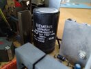
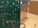
In order to avoid smoke-powered computing I'm replacing all the electrolytic capacitors in this 40-year-old PSU, as they seem to be originals. However, the biggest such capacitor in the PSU is proving very difficult to find, and I only need two or three of them, not two or three thousand!
The casing has the following printed on it:
B43306-E0227-T
220 uf an1 +50/-10%
385V-
-40...+85°C 03.85
DIN 41238

Siemens doesn't seem to be making these any more so I'd be most grateful for any suggestions as to what would be a suitable replacement for it.

Thanks in advance for any help and advice.
 

davenn

Moderator
Sep 5, 2009
14,474
Joined
Sep 5, 2009
Messages
14,474
just get another cap same value, same or higher voltage rating :)
 

alfredthegrape

Jun 22, 2026
6
Joined
Jun 22, 2026
Messages
6
For me it isn't quite as simple as that, as the existing capacitor has multiple pins (four or five) and I lack the knowledge to determine which pins do what. I'm aware that two pins at least are probably there to support such a bulky package reliably, but which two?
As this capacitor is no longer manufactured (at least by Siemens) I haven't been able to discover this information.
 

davenn

Moderator
Sep 5, 2009
14,474
Joined
Sep 5, 2009
Messages
14,474
For me it isn't quite as simple as that, as the existing capacitor has multiple pins (four or five)

show some well lit and sharp photos

you will probably find that several of the pins are just mounting pins to the PCB

cheers
Dave
 

bertus

Moderator
Nov 8, 2019
3,842
Joined
Nov 8, 2019
Messages
3,842
 

Attachments

  • B43306-E227-T.pdf
    309 KB · Views: 2

alfredthegrape

Jun 22, 2026
6
Joined
Jun 22, 2026
Messages
6
@davenn: The cap is still on the board as I don't want to start removing components before I have replacements to hand, so pictures of the pin side aren't possible at present. I attach a picture of it in situ but I suspect that it won't add any new information.

@bertus: The picture you posted does look very much like the kiddie, but the vendor is in the US and I'm in the UK. If I can't locate these capacitors for a sensible price over here then perforce I will have to source them from abroad. I was just hoping to avoid the lengthy wait imposed by transatlantic mail services.
 

Attachments

  • IMG_20260610_104722080_HDR.jpg
    IMG_20260610_104722080_HDR.jpg
    179.4 KB · Views: 6

alfredthegrape

Jun 22, 2026
6
Joined
Jun 22, 2026
Messages
6
@bertus:
Unfortunately the cap you mention is an axial component, and I require a radial one. It looks as though I'm going to have to bite the bullet and buy from the tedss.com site, delays and all.
 

davenn

Moderator
Sep 5, 2009
14,474
Joined
Sep 5, 2009
Messages
14,474
The cap is still on the board as I don't want to start removing components before I have replacements to hand, so pictures of the pin side aren't possible at present. I attach a picture of it in situ but I suspect that it won't add any new information.

well, if we cant seen the pins (even whilst it's still on the board) - then it's very difficult to help you
 

bertus

Moderator
Nov 8, 2019
3,842
Joined
Nov 8, 2019
Messages
3,842
Hello,

The datasheet i posted shows wich pin is positive and wich pins are negative.
Even an axial capacitor would be possible to use.
The positive can go through the pcb and the negative lead can be extended by soldering a wire to it and put the wire in the negative connection hole.

Bertus
 

Harald Kapp

Moderator
Moderator
Nov 17, 2011
14,282
Joined
Nov 17, 2011
Messages
14,282
Use insulated wire or cover blank wire by heat shrink tube to prevent any short circuits to neighbouring parts.
 

alfredthegrape

Jun 22, 2026
6
Joined
Jun 22, 2026
Messages
6
@davenn: Please see attached photo of the underside of the board the capacitor is soldered to.

@bertus: I'd be grateful if you would confirm that I've labelled the pinout correctly according to the PDF you kindly supplied. The solder pad in the middle of the terminals has no pin in it, so I'm assuming that it's empty/not connected.
I didn't realise that I could change the package of the capacitor - I thought that such things were written in stone at the design stage. This will make obtaining an equivalent capacitor much easier - many thanks.

@Harald Kapp: Thanks for the tip about insulating the wires if I use the axial option. You mention two approaches - insulated wire and heat-shrink tubing - is there any reason to prefer one over the other? I can do either.
 

Attachments

  • BigCapPins_202424299_MarkedUp1.jpg
    BigCapPins_202424299_MarkedUp1.jpg
    177.3 KB · Views: 4

alfredthegrape

Jun 22, 2026
6
Joined
Jun 22, 2026
Messages
6
I notice that the tolerance for the KON22145 component is +/-20%, whereas the original capacitor is +50/-10%
Is this something I should be concerned about?
 

Delta Prime

Jul 29, 2020
2,989
Joined
Jul 29, 2020
Messages
2,989
I notice that the tolerance for the KON22145 component is +/-20%, whereas the original capacitor is +50/-10%
Is this something I should be concerned about?
The printed nominal capacitance value, is not the actual value capacitance and will vary depending on circuit frequency. As long as you’re working voltage (WV)is the same or more than the original specifications. You have nothing to worry about you are well within tolerance.
 
Top