Splint3048
- Jul 31, 2026
- 2
- Joined
- Jul 31, 2026
- Messages
- 2
Hi,
I'm new to this forum and come from a mechanical engineering/motor mechanic background, so the question I'm about to ask is pretty basic.
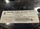
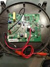
I have an Aldridge traffic light which I intend running with a 12V battery, but I powered the array directly via the red an black wires, bypassing the AC to DC circuit and the jumper wire (red one on the bottom image) got very hot, very quickly. The jumper wire is clearly a smaller gage wire but I did not expect it to get so hot so quickly.
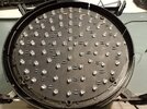
I've been doing a bit if research on this and it seems like I should be running a current limiting resistor but there are resistors built in (see image) so I assume they are the resistors.
Can anyone tell me what's going on with it and what I need to do to run it without damaging it?
Thanks
I'm new to this forum and come from a mechanical engineering/motor mechanic background, so the question I'm about to ask is pretty basic.
I have an Aldridge traffic light which I intend running with a 12V battery, but I powered the array directly via the red an black wires, bypassing the AC to DC circuit and the jumper wire (red one on the bottom image) got very hot, very quickly. The jumper wire is clearly a smaller gage wire but I did not expect it to get so hot so quickly.
I've been doing a bit if research on this and it seems like I should be running a current limiting resistor but there are resistors built in (see image) so I assume they are the resistors.
Can anyone tell me what's going on with it and what I need to do to run it without damaging it?
Thanks


