rainyliveshere
- Jul 4, 2026
- 35
- Joined
- Jul 4, 2026
- Messages
- 35
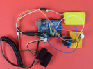
Hello. In 2019, I made this circuit using Seedstudio’s Grove-GSR sensor. I named it ‘Discomfort Alert’. This circuit measured the output of the sensor and showed it in the OLED display. When the output value crossed a threshold value, the buzzer made a sound. It made a sound when the person wearing the sensor needed to pee. I did this project keeping disabled patients and baby patients in my mind. The project was very close to my heart. The concept came when my only son who was 2.5 yr old that time was suffering from dengue. He was admitted in a hospital and the docs always told me to keep a record of his urine output. After coming back to my office from leave , I started this project.
The code-
I want suggestions to make the project usable in practical life. Yes, I wore it and tested my circuit but this arrangement is not useable for a real disabled person in real life. Another thing I noticed was, the threshold value could be different for different people in different environment. It looked like, I had to set the threshold value after testing on the individual who was going to wear it.
I am also thinking about replacing the breadboard with a custom PCB. That would make the device smaller and more reliable. I am considering using Card edge connectors to simplify module connections and improve the overall design. Do you think this is a good approach? Are there better connector options for a small wearable device?
Any suggestion for the betterment of this project is welcome.
The code-
C:
#include <SPI.h>
#include <Wire.h>
#include <Adafruit_GFX.h>
#include <Adafruit_SSD1306.h>
Adafruit_SSD1306 display;
const int BUZZER=3;
const int GSR=A0;
int threshold=0;
int sensorValue;
void setup(){
 long sum=0;
 Serial.begin(9600);
 pinMode(BUZZER,OUTPUT);
 digitalWrite(BUZZER,LOW);

 delay(1000);
 for(int i=0;i<500;i++)
 {
 sensorValue=analogRead(GSR);
 sum += sensorValue;
 delay(5);

 }
 threshold = sum/500;

 Serial.print("threshold =");
 Serial.println(threshold);
}
void loop(){
 int temp;
 sensorValue=analogRead(GSR);

display.begin(SSD1306_SWITCHCAPVCC, 0x3C);

  // Clear the buffer.
 display.clearDisplay();
 display.display();

 display.setTextSize(1);
 display.setTextColor(WHITE);
 display.setCursor(0,0);
 display.print("Threshold =");
 display.println(threshold);
 display.print("sensorValue =");
 display.print(sensorValue);
 display.display();
 display.clearDisplay();
 Serial.print("sensorValue=");
 Serial.println(sensorValue);
 Serial.print(",");
 Serial.print("Threshold=");
 Serial.println(threshold);

 temp = threshold - sensorValue;
if(abs(temp)>80)
 {
 sensorValue=analogRead(GSR);
 temp = threshold - sensorValue;
 if(abs(temp)>80){
 digitalWrite(BUZZER,HIGH);
 Serial.println("Go to toilet");
 delay(3000);
 digitalWrite(BUZZER,LOW);
 delay(1000);}
 }
}
I want suggestions to make the project usable in practical life. Yes, I wore it and tested my circuit but this arrangement is not useable for a real disabled person in real life. Another thing I noticed was, the threshold value could be different for different people in different environment. It looked like, I had to set the threshold value after testing on the individual who was going to wear it.
I am also thinking about replacing the breadboard with a custom PCB. That would make the device smaller and more reliable. I am considering using Card edge connectors to simplify module connections and improve the overall design. Do you think this is a good approach? Are there better connector options for a small wearable device?
Any suggestion for the betterment of this project is welcome.