Electric1's latest activity
-
Electric1 reacted to danadak's post in the thread Buck converter calculation does not match with LTspice results with
 Like.
A 1N914 is a small signal diode, so validity of your results would be in question in this type of application.
Like.
A 1N914 is a small signal diode, so validity of your results would be in question in this type of application. -
Electric1 replied to the thread Buck converter calculation does not match with LTspice results.Ok, which diode i can use to verify the result?
-
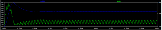
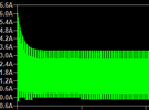
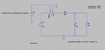
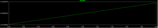
Electric1 replied to the thread Buck converter calculation does not match with LTspice results.Ok it works now if i replace the diode with 1N914 and the results are as expected of output voltage 15V and inductor currents.
-
-
Electric1 replied to the thread Buck converter calculation does not match with LTspice results.But the simulation does not run now i mean it takes lot of time and simulation does not stop.
-
-
Electric1 replied to the thread Buck converter calculation does not match with LTspice results.Sorry i think i missed the diode in my ltspice circuit.
-
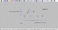
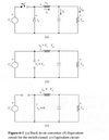
Electric1 replied to the thread Buck converter calculation does not match with LTspice results.The above is the circuit.
-
-
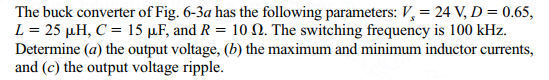
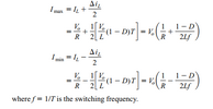
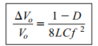
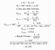
Electric1 posted the thread Buck converter calculation does not match with LTspice results in Electronics Homework Help.The below is the problem The formulas as per the textbook are I followed the above formulae and the calculations are as below To...
-
-
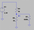
Rather confusing. Keep your equations in sync with the schematic. The equation uses V1, but your schemativ shows V4. Easy to spot in...
-
Electric1 replied to the thread Opamp circuit clarification.Yes used the super position and calculated the values, hopefully it is correct. But in the circuit i have left out few capacitors, i...
-
-
Electric1 replied to the thread Analysis of Op-amp circuit.Any help on the purpose of R5 resistor?
-
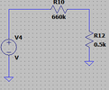
Electric1 replied to the thread Opamp circuit clarification.Yes i understand the superposition principle, the voltage at a point is the sum due to the voltage V1 with V2 removed and due to voltage...
-
I am analyzing the below op-amp circuit. my main worry is with the R5 resistor, in absence of R5 and Vin = 10V, Vout=...
-
-
Electric1 replied to the thread Opamp circuit clarification.Thank you so i will assume that the voltage at the noninverting input is the voltage sum of the V3 and V4 based on super position...
-
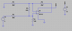
Solve your circuit using superposition to make life easier.....? In your modified circuit I get -
-
You are running a transient solution, 10 mS, is the OP747 settled yet given the internal compensation C and other miller effects of...